20th Annual International Esri User Conference, San Diego, Cal. June 26th-30th, 2000
Authors Names:
Prof. Dr. Jörg Schaller, Esri Germany, PbS
Dr. Uwe Lohr, TOPOSYS GmbH
Karl Mannheim, Rotorflug GmbH
Thomas Hack, PbS
New GIS and Laserscanning Methods for Monitoring Powerline Utilties
Abstract
Energy providers need detailed information about the location and the present technical status of their facilities network. Energy lines often follow rough terrain and therefore permanent monitoring and acquisition of accurate and current data and their management is mandatory.
Esri Germany, TOPOSYS and Rotorflug developed a new technology by integrating airborne laserscanner data into a GIS-based "Powerline Management Information System". The combination of several basic technologies provided by the consortium meets above requirements on accuracy and provides easy access on the database. In more details the system features:
The described system solutions are open and compatible. According to clients requirements the provision of pure data, consulting, the software of the Powerline Management Information System or the turnkey complete system (incl. training and maintenance of client’s staff) is available.
Introduction
The TopoSys laserscanner system is designed to produce digital elevation models (DEMs) of the environment at a typical accuracy of 0.5 m in x, y and 0.15 m in z. The exceptional measurement frequency of 83000 measurements per second results in about five measurements per m˛ on ground, when surveying from an aeroplane – from a helicopter the measurement density is even higher. This measurement density and the regular scan pattern (parallel lines) form the basis for high quality DEMs.
In the recent years an increasing demand on high-precision digital elevation models (DEMs) has to be noted - high-precision in this sense means that the accuracy of the DEMs is better than 1m in x,y and about 0.2m in z. Many of those applications not only request for high precision, but also demand a short delivery time. Typical applications are monitoring of coastal erosions, simulation of floods in river basins in order to determine engineering works, and simulation of emitter sites or line-of-sight calculations for mobile communication networks.
The TopoSys laserscanner system integrated into a fixed wing aircraft has delivered thousands of km˛ of high resolution DEM for such applications. Recently the TopoSys system has been mounted into a helicopter to start a new application: Integrated Helicopter Corridor Mapping.
Description of the System
All the various sensor data (see also Figure 1) are recorded digitally during the laser scanner survey. LINS, GPS, laser data and RGB linescanner data are stored on exchangeable PC harddisks, only video data are stored on a digital tape. During the survey the operator controls the performance of the system, in case of the laser data with help of a real-time waterfall display.
GPS data is registered with help of a Novatel Millennium L1/L2 receiver at a data rate of 1 Hz, while the high precision LINS (Laser Inertial Navigation System) collects position and attitude data at a data rate of 64 Hz. After flight path restitution and merging of dGPS and LINS measurements, position and attitude data are available at 64 Hz.
Fig.1 IHCM System Components
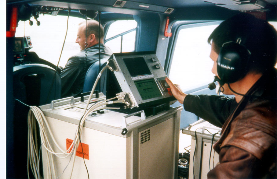
Fig.2 Equipment mounted in a helicopter for on flight operation
The eye-safe laser sensor operates at 1.54 µm, a pulse rate of about 83 kHz and a scan frequency of 630 Hz. The scan angle is fixed to +/- 7° in order to minimise shading effects especially at the borders of the scan. From a survey altitude of 1000 m the swath on ground is about 250 m. Swath width – and measurement density – can be adapted by selecting the appropriate the survey altitude.
The down-looking video camera, which was part of the sensor package up to now, is replaced by a four-channel linescanner (R, G, B, IR). The linescanner provides a pixel size of about 0.4 m from a survey altitude of 1000 m and allows generating "ortho-photos" of the survey area. The line-scanner data are expected to support the identification of vegetation, too.
The application "Integrated Helicopter Corridor Mapping (IHCM)" is done from a helicopter like a Bell Jetranger 206. In case of IHCM, a 45° forward looking digital video camera additionally records a video sequence of the surveyed tracks (see also Figure 3). Typically survey altitudes in IHCM applications are between 200m and 500 m above ground.

Fig.3 IHCM Sensor package in a helicopter
The off-line data processing is done by high-end PCs. Key software packages are a package for flight path restitution and the TopoSys software for DEM generation and post-processing; IHCM post-processing is made by a special package in ARCINFO and ERDAS environment.
The present TopoSys I system will be replaced by the TopoSys II series in late autumn 1999. Performance parameters of TopoSys II are given in the following table.
Table 1. Performance Parameters of TopoSys II
|
sensor type |
pulse modulated laser radar |
|
range |
» 1’600 m |
|
scanning principle |
fibre optic line scanner |
|
transmitter |
solid state at 1.5 µm |
|
measurement principle |
run-time measurement, intensity, first + last pulse |
|
laser pulse rate |
83’000 Hz |
|
scan frequency |
630 Hz |
|
field of view |
+/- 7° |
|
number of pixels per scan |
127 |
|
swath width (at 1’000 m flight height) |
250 m |
|
resolution of a distance measurement |
< 0.03 m |
|
height accuracy of TopoSys DEMs |
< 0.15 m |
|
laserscanner classification |
class 1 by EN 60825 (eye-safe) |
Integrated Helicopter Corridor Mapping
"Integrated Helicopter Corridor Mapping" (IHCM) is an application developed by TopoSys GmbH, Esri Germany and Rotorflug to survey medium and high voltage powerlines. IHCM integrates airborne laserscanner data into a "Powerline GIS- and Management Information System". Depending on a client’s requirements a spectrum of services is available, from the delivery of the pure data to turnkey systems including maintenance and training of staff.
Fig.4 Data gathering and Processing System
Fig.5 DEM Of A Medium Voltage Powerline
Figure 5 shows the DEM of a medium voltage powerline as relief presentation. Cross sections and trans-sections may be generated to visualise the distance of vegetation to powerline. However, only line parameters are extracted interactively, the vegetation distance map and the vegetation management plan is created mainly automatically.
Fig.6 Laserscanner and CAD data, video scene
The example on Figure 6 shows laserscanner data as background information in a "Powerline and Vegetation Management System". Hotlinks allow cross-references such as links to databank information on CAD drawings of poles or to the video scenes recorded by the 45° forward looking camera.Another output of the system is a "Vegetation Management Plan" which provides medium term clear-cutting information derived from laserscanner data and vegetation growth classes.
Fig.7 Vegetation management plan
References:
Lohr,U.; Schaller,J.1999: High Resolution Digital Elevation Models for various Applications.
Proceedings of the Fourth International Airborne Remote Sensing Conference and Exhibition/21st Canadian Symposium on Remote Sensing.VolumeI, pp I-247-I-253,Ottawa,Ontario,Canada,Publisher:ERIM Interntl..Inc.,1999, ISSN 1076-7924,U.S.A.
Lohr,U.; Schaller,J..1999: Trassenbefliegungen mit dem TopoSys Laserscanner, GIS
Geoinformationssysteme, 2/99,3-5,Wichmann-Hüthig,ISSN 0953-1523,Heidelberg
Authors and Contact Information:
Prof.Dr. Joerg Schaller
Scientific Director
Esri Germany
Ringstrasse 7
D-85402 Kranzberg, Germany
Phone: +49-8166-677-0
Fax: +49-8166-677-111
Email: J.schaller@Esri-Germany.de
Dr .Uwe Lohr
TopoSys GmbH
Managing Director
Freiherr-vom-Stein-Str. 7
D-88212 Ravensburg, Germany
Phone: +49-751-36605-0
Fax: +49-751-36605-31
Email: info@toposys.com
Karl Mannheim
Managing Director
ROTORFLUG GmbH
Peter-Geibel-Strasse
D-61365 Friedrichsdorf
Phone: +49-6007-9141-0
Fax: +49-6007-9141 - 24
Thomas Hack
Planning Bureau Prof.Dr. Joerg SchallerEsri Germany
Ringstrasse 7
D-85402 Kranzberg, Germany
Phone: +49-8166-6868-0
Fax: +49-8166-6868-11
Email: t.hack@pbs-schaller.de
URL: www.pbs-schaller.de