
Technology Service Corporation announces LOGSPOT: a tool to assist tactical logistic commanders with daily operations. The tool is being developed for the Army Research Laboratory as an extension for ArcView 3.x. Phase 1 demonstrated concepts for ammunition. The system will feature: 1) Import, entry and manipulation of terrain, infrastructure and logistic data, 2) Manual and pseudo-automated vector database generation, 3) Site selection, accounting for slope, drainage and proximity factors, 4) Site layout, accounting for slope, drainage, safety and other doctrinal factors, and 5) Site operation, including shipping/receiving, and site management. A Phase 2 prototype, applicable to a wider range of problems, is being developed.
Problem: The Army currently has no tool for combining map and logistic data to assist tactical planners in their site planning, layout and operations.
The ability to rapidly adapt mission plans is key to operational success on the modern battlefield. Although this is particularly true for front-line combat forces, long-term front-line success also requires a fully capable and aware force sustainment structure. Therefore this ability is equally critical for logistics and Combat Service Support (CSS). On the digital battlefield of the 21st century, the technologies necessary to achieve rapid adaptation to changing conditions include:
These emerging technologies are being combined in TSC's Logistics Site Planning and Operation Tool (LOGSPOT) that logistics commanders and their staffs (at all levels of command) can use to intuitively optimize the layout of logistics sites and plan daily operations. Rather than relying on paper maps, plastic overlays and grease pencils, this tool is being made fully digital: capable of integrating the information from electronic intelligence reports, radio frequency (RF) supply tags, vector and raster terrain data as well as imagery and tabular data from legacy systems and manual procedures. The tool takes advantage of relatively inexpensive, personal computer (PC) based commercial off-the-shelf (COTS) Esri software that is both easy to use and network, allowing the free and timely flow of logistics information up and down the chain of command. TSC’s LOGSPOT concept, illustrated in Figure 1, will allow logistics planners to create plans based on terrain considerations, customer requirements, logistics operating rules, safety and enemy threat by integrating the types of information shown. These data are readily combined and displayed using Esri’s ArcView GIS (v3.x).
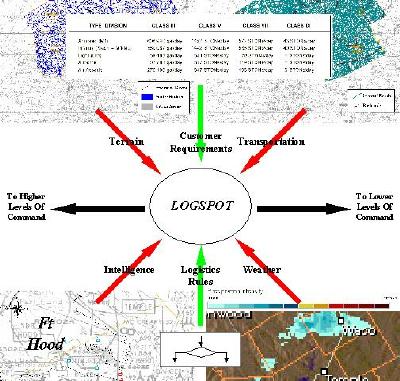
Figure 1 Illustration Of LOGSPOT Concept
The current Small Business Innovation Research (SBIR) Phase 2 development effort was preceded by a Phase 1 effort where: basic LOGSPOT concepts were demonstrated, and a large part of the LOGSPOT conceptual framework was defined. A roadmap for the Phase 2 effort is shown in Figure 2, and the set of LOGSPOT goals include:
As shown in Figure 3, the LOGSPOT is being designed as a theater-wide tactical logistic tool. The vision (for a fielded version) is a network of LOGSPOT workstations at the various levels of command and logistic sites throughout the theater. Therefore, the LOGSPOT network is based on a hierarchical infrastructure tree that parallels the command structure of the theater force. The infrastructure tree includes the following entity types (for each logistic commodity supported):
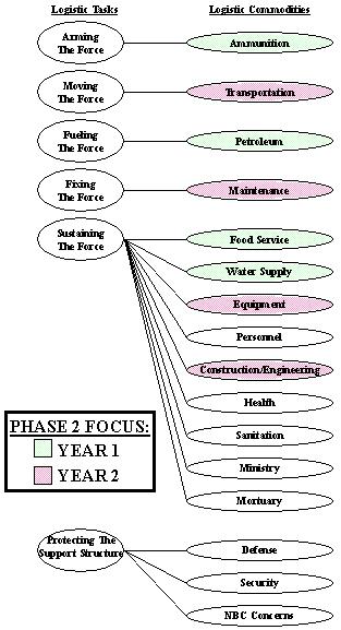
Figure 2 Phase 2 LOGSPOT Roadmap
With regard to logistic planning in general, there are essentially two types of supply systems employed: "Push", and "Pull"[1]. In a "Push" system, supply quantities are estimated at higher echelons and delivered (pushed) down to the lower ones. This type of system is generally used at theater start-up. In a "Pull" system, supplies are consumed at lower echelons and requested (pulled) from the higher ones. This type of system is used in "mature" theaters. The LOGSPOT emulates/supports this push-pull strategy in the following manner:
![Figure 3 Illustration Of LOGSPOT Operational Area[1]](p05835.jpg)
Figure 3 Illustration Of LOGSPOT Operational Area[1]
A schematic of the LOGSPOT infrastructure tree is shown in Figure 4. This structure is maintained in a directory tree on each LOGSPOT workstation. Each entity in the infrastructure tree is assigned to a directory (and LOGSPOT project) within the corresponding directory structure. Although the entire directory structure is maintained on each LOGSPOT workstation (to allow each LOGSPOT node to have "knowledge" of all other nodes), in general only an entity’s assigned directory will be populated on each local machine. The sample theater scenario for the Phase 2 development is illustrated in Figure 5, and the corresponding infrastructure directory tree is shown in Figure 6.
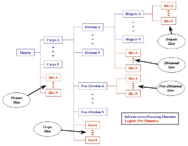
Figure 4 Schematic Of LOGSPOT Infrastructure Planning Tree
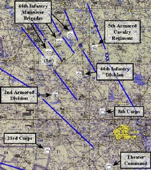
Figure 5 Phase 2 LOGSPOT Sample Scenario
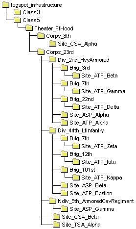
Figure 6 Infrastructure Directory Tree For Scenario Of Figure 5
The LOGSPOT consists of two interface levels: 1) project-level (with project window suppressed), and 2) overlay-level (variations on the ArcView view document). Users are not allowed direct access to any of the underlying ArcView document types (via the project window), but are allowed access to the LOGSPOT project- and overlay-level interfaces via LOGSPOT-specific controls. Hence, direct interaction of much of the out-of-the-box ArcView functionality is disabled in the LOGSPOT (although many functions are embedded in the LOGSPOT-specific controls). To meet Army requirements, the LOGSPOT interface is being designed to: 1) present minimal controls to the operator at any one time (this is being accomplished through the use of nested user- and function-specific control sets), and 2) utilize military symbology and terminology as much as possible. The current LOGSPOT is being designed to support the following set of overlays:
With regard to the use of military symbology, Figure 7 shows some of the unit and logistic commodity symbols currently supported. The numerous terrain feature symbols were all defined from reference [2].
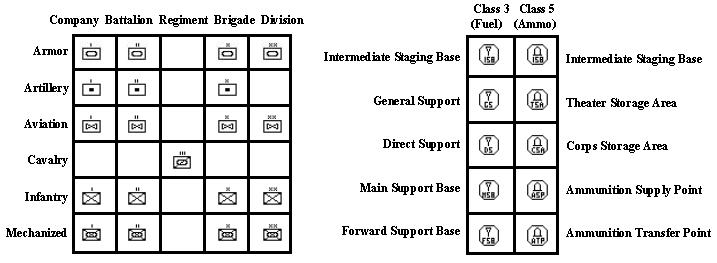
Figure 7 Sample LOGSPOT Unit And Logistic Commodity Symbols
Although the availability of high quality terrain data for analysis support is still fairly limited, the Phase 2 LOGSPOT is being designed to support as many digital data formats as possible. The Phase 1 LOGSPOT supported only Vector Smart Map level 0 (VMAP0) and Arc Digitized Raster Graphics (ADRG) formats. The Phase 2 LOGSPOT is being designed to support the expanded set of data types listed below, many of which are available on the National Imagery and Mapping Agency’s (NIMA’s) Fort Hood prototype CD (made available to TSC through the Army):
Figure 8 shows the tile boundaries for the raster and image data types available for the region around the Phase 2 LOGSPOT sample scenario. In the figure, the Cadrg_conc, Cadrg_cjog, and Cadrg_ct50 themes represent the 1:1,000,000, 1:250,000, and 1:50,000 resolution data, respectively. In addition, VMAP0 is available for the entire area as well as limited amounts of FFD, DTOP and VMAP2. Because of the potential size of terrain databases, the vision is to distribute the required data sets to each LOGSPOT node via CD-ROM. The distribution and installation of the required terrain data sets is expected to be a pre-deployment activity.
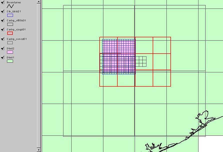
Figure 8 Raster And Imagery Data Set Tile Boundaries For Sample Scenario Region
 5.0 LOGSPOT Analysis Capabilities
LOGSPOT is being designed to support a variety of analysis activities, including: 1) LOGSPOT administration, 2) Site Suitability/Critique, 3) Site Layout, 4) Site Operations, and 5) computer-aided feature extraction. Each of these analysis activities is discussed briefly below.
LOGSPOT administration includes maintenance/update of the infrastructure tree (e.g., changing passwords, adding/deleting users/sites, etc.), maintenance/update of the supporting information base (terrain and unit data, etc.), and administration of the rule base (adding/deleting/modifying rules). A summary of the LOGSPOT fuzzy rule operators is provided in Figure 9. Because of the nature and physical shape of these fuzzy operators, the descriptions and parameters are based on a digital filter paradigm (e.g., stop and pass bands). The rule base format also supports standard relational and Boolean crisp operators.
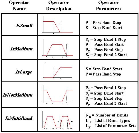
Figure 9 LOGSPOT Fuzzy Rule Operators
LOGSPOT terrain feature extraction capabilities are being included to allow the import and use of digital data in areas where no "authorized" digital data sources exist. The Phase 1 LOGSPOT encapsulated ArcView’s native on-screen digitization capabilities in a manner consistent with the LOGSPOT operating procedures. Although this capability is being retained in the Phase 2 prototype, TSC is investigating semi-automated terrain feature extraction from maps. TSC has several years of experience in the development of image interpretation tools and is currently working to integrate this technology into the Phase 2 LOGSPOT.
The LOGSPOT’s Site Selection/Critique goal includes suitability analyses to support selection or critique of the physical boundaries for a logistic site. This concept is illustrated in Figure 10. The multiple factors taken into account in the suitability analysis include: 1) terrain slope, 2) drainage, 3) Euclidean proximity to nearby installations, 4) road network proximity to friendly units being supported, and 5) engineering support considerations (for example, rough estimates of the amount of clearing, grubbing and earth moving required for site preparation). As shown in the figure, Site Selection results in site boundary specification, while Site Critique works backward to estimate the suitability of a previously specified site boundary.
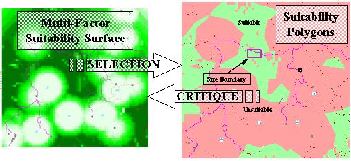
Figure 10 Illustration Of LOGSPOT Site Suitability/Critique Analyses
The LOGSPOT’s Site Layout goal includes: 1) suitability analyses to support fine suitability within the site boundary (as opposed to the coarse suitability performed during Site Selection), and 2) a variety of layout rules for the various site areas (e.g., office, storage, etc.). For the Class V ammunition commodity, these rules include Quantity-Distance (QD) safety factors. These factors are obtained via LOGSPOT interaction with the Explosives Safety Suite (ESS) QD Calculator. The ESS QD Calculator is a joint service tool authorized by the DoD for determining safe distances from Potential Explosive Sites (PESs), and encapsulates the QD rules of reference [3]. Figure 11 illustrates the analysis concepts associated with the LOGSPOT Site Layout goal.
For the Class V ammunition commodity, the LOGSPOT’s Site Operations goal includes analysis capabilities that support the receipt, storage and issue of ammunition. This includes overseeing incoming and outgoing ammunition transactions (shipments), as well as monitoring the status of individual storage areas and ammunition stacks. The information components associated with these analyses include databases of supported National Stock Numbers (NSNs), Department of Defense Identification Codes (DODICs), and transport/storage information (e.g., pallet sizes, numbers of rounds per pallet, pallet dimensions, etc.). Some of the Site Operations entities are illustrated in Figure 12.
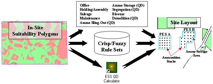
Figure 11 Illustration Of LOGSPOT Site Layout Analysis Concepts
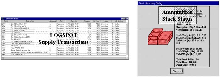
Figure 12 Illustration Of LOGSPOT Site Operations Elements
The Phase 1 LOGSPOT operated in a stand-alone configuration, and was hosted on a single machine. In order to provide more robust operation in the severe battlefield environment, this mode of operation is being retained. Thus, LOGSPOT avoids dependence on a continuous connection to remote resources and a reliable tactical network. Remote resources may be accessed, but can be stored locally prior to proceeding with analyses.
However, the ability of the Phase 2 LOGSPOT to operate in a stand-alone mode does not obviate the need for a network operating mode as well. Since each workstation represents a single node in a command hierarchy, the LOGSPOT concept supports network operation for data dissemination and collaborative logistic planning. The details of LOGSPOT network operation are still under development, but the evolution of the envisioned LOGSPOT operating environment is summarized in Figure 13.
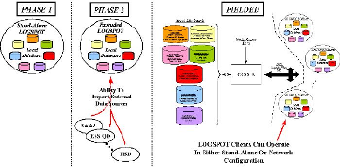
Figure 13 Evolution Of Envisioned LOGSPOT Operating Environment
In addition to the Phase 2LOGSPOT effort described above, TSC is performing a separate Phase 1 Army SBIR effort to investigate the integration of software agent technologies into the LOGSPOT. Software agents can be useful to the LOGSPOT by providing assistance in the areas of:
Some specific software agent applications that TSC is investigating include:
The software agent concept being demonstrated in the Phase 1 involves the automated monitoring and re-supply of an M1A1-equipped tank battalion. The interplay between agents and the LOGSPOT is illustrated in Figure 14.
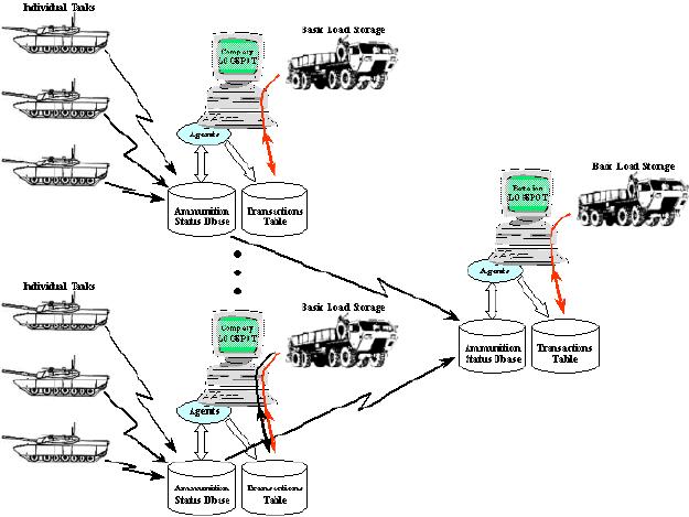
Figure 14 Software Agent/LOGSPOT Interplay In Sample Application
TSC is developing a tactical-level decision aid for logistic planning at all levels of command and for multiple logistic commodities within a combat theater. The tool is being built on ArcView 3.x technology, including the Spatial Analyst and Network Analyst extensions. An interim demonstration of the software supporting the Class V ammunition and Class III fuel commodities is planned for early 2002. Final release of the prototype tool to the Army is planned for early 2003, and will support several additional logistic commodities including service commodities like Class IX maintenance. LOGSPOT demonstrations will involve significant end-user interaction, and validation in an Army operational exercise if possible.
The work described in this paper is being funded under a Phase 2 SBIR effort for the Human Research and Engineering Directorate of the U.S. Army Research Laboratory (ARL) at Aberdeen Proving Ground, MD. Mr. Peter Grazaitis is the ARL program manager for the LOGSPOT effort.
The LOGSPOT software agent insertion effort discussed in Section 7 are being funded under a separate Phase 1 SBIR for ARL. Mr. Timothy Hanratty is the ARL program manager for this SBIR effort.
The ESS QD Calculator software was made available by the Defense Ammunition Center located with the McAlester Army Ammunition Plant at McAlester, OK. The ESS software is a joint service effort. Mr. Lyn Little is the Army program manager, and Mr. Phillip Wager represents the Navy via the Naval Facilities Engineering Service Center (NFESC).
1. Army Field Manual FM 100-10, "Combat Service Support," Headquarters Dept. of the Army, 3 October, 1995.
2. MIL-PRF-89045, "Performance Specification: Geospatial Symbols for Digital Displays (GeoSym)," National Imagery and Mapping Agency, 20 February, 1998.
3. Department of the Army Pamphlet 365-84, "Ammunition And Explosives Safety Standards," Headquarters Dept. of the Army, 15 December, 1999.
