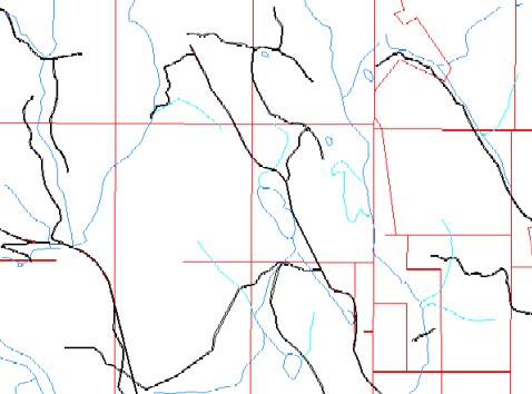
Figure 1: 2.64-inch-to-mile scale map

Figure 2: 1/2-inch-to-mile scale map
This paper presents GENERALIZE2, a tool developed by the author to resolve spatial conflicts between linear features in a map. When the scale of a map is reduced, the symbology of linear features often overlap one another. For instance, on a half-inch-to-a-mile map roads often follow streams so closely that their symbols cross. This is why the tool was developed. Where line symbols overlap, the tool adjusts the spatial location of the lines to resolve the conflict. This helps to automate map production.
The USDA Forest Service Geospatial Service and Technology Center (GSTC) in Salt Lake City, Utah have been making maps for years. The map production traditionally has involved a lot of manual work. This work is time consuming. For this reason GSTC is developing procedures to automate map production to a greater extent. GSTC makes maps at different scales. Their base maps are 2.64"-to-a-mile, the standard scale of the U.S. Geological Survey (USGS) 7.5' topographic maps. The line work for these maps is stored in a digital database. GSTC also makes maps at reduced scales, for example 1/2"-to-a-mile Forest visitor maps. If the same database could be used to produce maps at both scales, this would save time, but doing so is problematic. One of the problems is that when the scale is reduced the lines are closer together. Since some line symbols have width, e.g. roads, when the lines are closer, then their symbols will sometimes overlap or become crowded (unless the widths of the symbols are also reduced.) For example, where a road parallels a stream it may appear that the stream is flowing down the middle of the road. This is not desirable. Currently this problem is handled manually by separating the lines so that their symbols do not overlap. This takes a lot of time, so GSTC hired the author to develop a tool to automate this process. The tool is named GENERALIZE2.
Figure 1: 2.64-inch-to-mile scale map |
Figure 2: 1/2-inch-to-mile scale map |
Figure 1 is a section of a 2.64"-to-a-mile base map. The roads are black, the streams blue, and the land survey lines red. Figure 2 depicts the same area when mapped at 1/2"-to-a-mile. (For the purpose of display the image is enlarged to be the same size as Figure 1. But in actuality the width of the road symbols on both maps is the same.) Figure 2 displays how the lines symbols can overlap or become crowded when the map scale is reduced. Roads overlap streams and other roads.
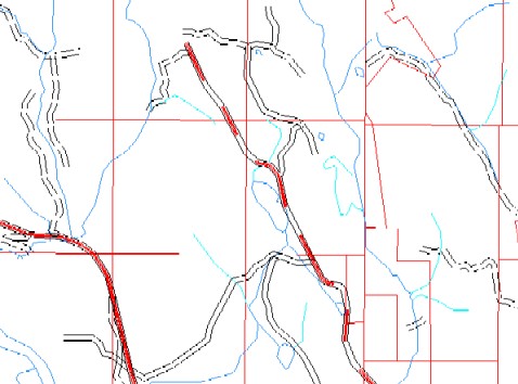 Figure 3: Before GENERALIZE2 |
 Figure 4: After GENERALIZE2 |
GENERALIZE2 was written to resolve spatial conflicts between linear features in a map. In this example (Figure 4), the streams were not altered, but instead were used as a {block_cover}, and the roads were displaced. As a result the roads and streams are no longer crowded.
GENERALIZE2 generalizes the arcs in a line coverage. It is similar to the ARC GENERALIZE command (BENDSIMPLIFY option), except that in the process of generalizing arcs it also moves them to resolve spatial conflict with other arcs, a la OVERPOSTing. GENERALIZE2 is an AML. It runs from the GRID module of ArcInfo.
Usage: GENERALIZE2 <in_cover> <out_cover> <arc_move_item> <node_move_item> <buffer_distance> <cell_size> {block_cover} {block_buffer} {weed_tolerance} {JOIN | NOJOIN} {sequence_item | ANGLE | DENSITY} {split_tolerance}
In brief the arguments are:
<in_cover> - the input arc coverage.
<out_cover> - the name for the output coverage.
<arc_move_item> - the item in the <in_cover> AAT that indicates which arcs can be moved.
<node_move_item> - the item in the <in_cover> NAT that indicates which nodes cab be moved.
<buffer_distance> - the minimum desirable distance between arcs in the <out_cover>.
<cell_size> - the processing grid cell size. (GENERALIZE2 does its processing in the raster environment.)
{block_cover} - the input arc coverage whose lines will be used to alter the locations of the arcs in the <out_cover>.
{block_buffer} - the minimum desirable distance from arcs in the <out_cover> to arcs in the {block_cover}.
{weed_tolerance} - the weed tolerance used by ARC GENERALIZE (BENDSIMPLIFY option) to generalize the <out_cover> arcs.
{JOIN | NOJOIN} - whether or not to join the <in_cover> AAT attriutes to the <out_cover>.
{sequence_item | ANGLE | DENSITY} - how to sequence the arcs in the <in_cover>.
sequence_item - a numeric item in the <in_cover> AAT that is used to sequence the input arcs.
ANGLE - the input arcs are sequenced using angle of intersection. First the arcs are grouped by constructing paths through the input arcs. The path taken is that which deviates least from the current direction of travel. In this way, arcs that are more likely to be associated with each other (e.g. roads that are part of the same route) are grouped together and processed in sequence.
DENSITY - the input arcs are sequenced in descending order based on the density of lines in the <in_cover> and {block_cover}. In this way, arcs in more crowded areas are processed first.
{split_tolerance} - the weed tolerance used when determining where to split the input arcs prior to generalization. This is done by running ARC GENERALIZE (POINTREMOVE option) on a copy of the input arcs using the {split_tolerance} as the weed tolerance. The vertices remaining are used to split the original input arcs.
GENERALIZE2 resolves conflict between linear features in a multi-step process:
1 SPLIT - All of the input arcs are split at major bends. What constitutes a major bend is determined using the {split_tolerance} in conjunction with the ARC GENERATE command. The reason for splitting the arcs is because GENERALIZE2 does not address the spatial conflict of an arc with itself, e.g. switch-backs in a road. Once the arc is split at the bend, then GNERALIZE2 will check for conflict between the two new arcs.
2 SEQUENCE - All of the input arcs are sequenced in order of importance. Arcs that shouldn't be moved as much should come first. For example, major roads should generally be processed before minor roads that branch off of these major roads. There are three different methods for sequencing arcs: {sequence_item | ANGLE | DENSITY}.
3 GRID - First each input arc is gridded using the specified <cell_size>. In so doing this generalizes the form of the arc. Specifying a smaller <cell_size> will retain more definition, but will lengthen the processing time.
4 MOVE NODES - If either node at the ends of each arc is within the <buffer_distance> of all previous arcs (inlcuding those in the {block_cover}), then the node is moved outside of the buffer. (Each node in the cover can only be moved once.)
5 RECONSTRUCT - The path of each arc is reconstructed by finding the least-cost path between the nodes at either end of the arc. The cost surface for this analysis is created by summing A) a buffer of the arc with B) a buffer of all previous arcs (including those in the {block_cover}.) The radius of the buffers is set equal to <buffer_distance> (except for {block_cover} arcs that are buffered with a radius equal to the {block_buffer}.) Both buffers are assigned cost weights. The "A" buffer weights start at 0 in the center and increase to 7 at the perimeter. The "B" buffer weights start at 15 in the center and decrease to 1 at the perimeter. (The weights are increased by a factor of 1.5 where the buffers from two or more previous arcs intersect.) In addition to the cost surface, a horizontal factor grid is used to make it easier to cross the "B" buffer on a diagonal than it is to move through it in a perpendicular or parallel direction.
6 VECTORIZE - The least-cost path is then vectorized to create a new arc. Steps 3-6 are repeated for each arc in the coverage.
7 GENERALIZE - Finally all of the new arcs are GENERALIZEd (using the BEND SIMPLIFY option) so that they are smoother.
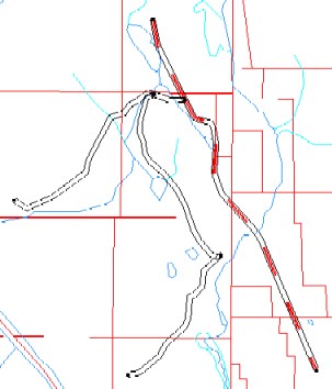 Figure 5: Split input arcs |
The first thing GENERALIZE2 does is to split the input arcs at major bends. What constitutes a major bend is determined using the {split_tolerance} in conjunction with the ARC GENERALIZE command. In this example (Figure 5) the central arc is split. It was probably not necessary to split this arc.
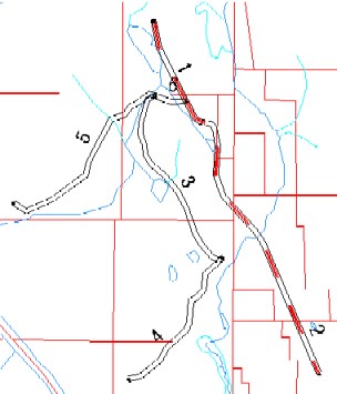 Figure 6: Sequence input arcs |
Next the arcs are sequenced in order of importance. Arcs that shouldn't be moved as much should come first. There are three methods for sequencing arcs: {sequence_item | ANGLE | DENSITY}. In this example (Figure 6) the ANGLE option was used. The main road (a secondary highway) has the highest priority.
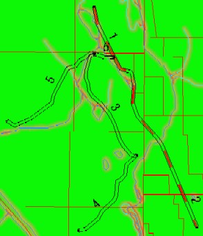 Figure 7: Grid block arcs |
Before processing the arcs in the input coverage, the initial cost surface is created by gridding the {block_cover} and buffering it using the {block_buffer}. The cost assigned to this buffer starts at 15 in the center (red) and decreases to 1 at the perimeter. In this example (Figure 7) the {block_cover} contains streams and waterbody boundaries, and the {block_buffer} is 300 feet. (The green background has a cost of 0.)
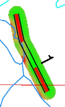 Figure 8: Before GENERALIZE2 |
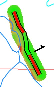 Figure 9: After GENERALIZE2 |
Next the input arcs are processed. Each arc is gridded, and buffered using the <buffer_distance>. The cost assigned to this buffer starts at 0 in the center and increases to 7 at the perimeter. This cost surface is added to the main cost surface created from the {block_cover} to create a temporary cost surface that will be used to process this input arc. (In Figures 8 & 9 the area of least cost is green, and the area of greatest cost is red. Outside of the buffer the cost is 99. This effectively prevents the arc from being moved further than the <buffer_distance>.) Then the GRID COSTPATH function is used to reconstruct the arc's path, finding the least-cost path between the nodes at the ends of the arc. In this example (Figure 9) the road is moved away from the waterbody line. Finally the new arc location is buffered, assigned an inverse weight from 15 to 1, and added to the main cost surface. In this way each input arc is checked for conflict, not only with the arcs in the {block_cover}, but also with all previous input arcs.
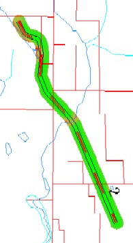 Figure 10: Before GENERALIZE2 |
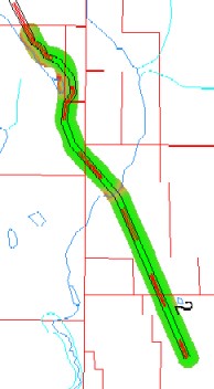 Figure 11: After GENERALIZE2 |
Processing moves to the next arc (Figures 10 & 11). Once again GENERALIZE2 moves the road away from a waterbody.
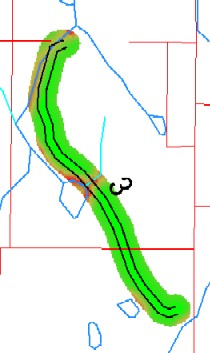 Figure 12: Before GENERALIZE2 |
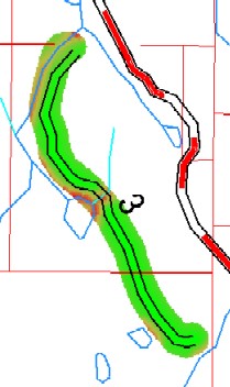 Figure 13: After GENERALIZE2 |
This example (Figures 12 & 13) shows how the node at the top of the arc is also moved away from the stream line.
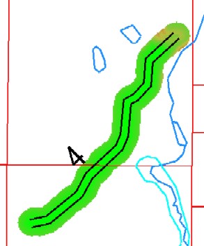 Figure 14: Before GENERALIZE2 |
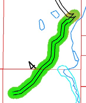 Figure 15: After GENERALIZE2 |
 Figure 16: Before GENERALIZE2 |
 Figure 17: After GENERALIZE2 |
In this way the GENERALIZE2 tool is successful at displacing the roads so that their symbols don't overlap or crowd the symbols of streams or other roads. However, are the results up to cartographic standards?
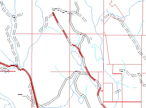 Figure 18: GENERALIZE2 |
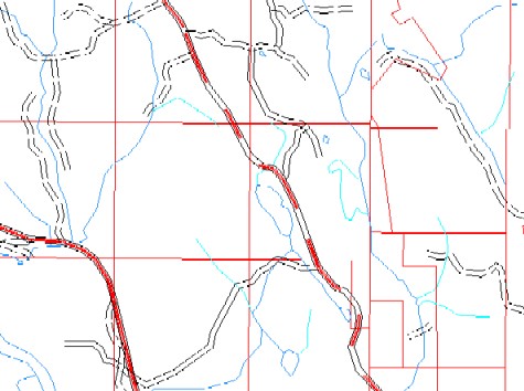 Figure 19: Manual generalization |
In this area (Figures 18 & 19), the results from GENERALIZE2 compare favorably with the manual generalization that has been done in the past. And the cartographers are satisfied with the preliminary results. However, one noticable difference is that GENERALIZE2 sometimes changes the shape of arcs more so than did the manual process. The most evident example of this is the bend in the primary highway (solid red) on the left side of the display. GENERALIZE2 adds a crook in the highway to avoid the junction of two streams. The manually generalized line keeps its shape, but crosses the junction. Perhaps an ideal solution would keep the shape of the line while still moving it away from the junction. So GENERALIZE2 could be enhanced, but the cartographers expect that some manual edits will be necessary in any event.
NOTES: In Figure 19 there are extra roads shown at the top of the display because a different window was used to select the roads. On the other hand, in Figure 19 there is one less road shown at the bottom of the display. Presumably this is because the road was dropped when the roads were manually generalized.
The greatest weakness with GENERALIZE2 is that it is very slow. In tests it has taken 1 to 2 minutes to process each input arc. The reason for this is that a dozen or so GRID functions are run on every arc (Steps 3-6 of the process). The GRID functions themselves are fast, but chaining them together like this causes many files to be read and written, and this is very inefficient. Because of this the author is rewriting this part of the process in C so that all of the arcs will be processed within one executable. Hopefully this will cut down the processing time from minutes to seconds per arc.
Once GENERALIZE2 is rewitten, then more tests will be run. Assuming the results are satisfactory, GENERALIZE2 will go into production, helping to produce maps at a reduced scale from a central digital database.
Esri, ArcINFO and ArcDoc.
Seminar or On-demand Mapping, Barcelona, 21-23 September 2000 ( http://www.geo.unizh.ch/ICA/Documents/Joint_2000).
US Forest Service, Geospatial Service and Technology Center ( http://www.fs.fed.us/gstc).
GENERALIZE2, and many other AML tools, can be downloaded from http://www.reo.gov/digitalvisions. From the main page click on [Tool Development], and then click on either [List All Tools] or [Feature Automation & Update]. Finally, click on the button to the left of GENERALIZE2 to download the tool.
Let me know if you have any questions, problems, ideas, etc.