Submitted Abstract:
As the Orange County Sanitation District (OCSD) adopts GIS, they are faced with the challenge of integrating CAD data from design Consultants into a Facility Model. OCSD is in the midst of a $1.6 billion Capital improvement program resulting in dramatic changes to their two treatment facilities and regional collection system. This presentation will focus on the methodology developed to move data bi-directional between GIS and CAD, what and how a facility model works, why standards and procedures are crucial to maintaining an accurate as-is condition of the facility and how data is exchanged between the District and design consultants.

As the Orange County Sanitation District (OCSD) adopts GIS, they are faced with the challenge of integrating CAD data from design consultants into a Facility Model. OCSD is in the midst of a $1.6 billion capital improvement program resulting in dramatic changes to their two treatment facilities and regional collection system. This presentation will focus on the methodology developed to move data bi-directionally between GIS and CAD, what a facility model is and how it works, why standards and procedures are crucial to maintaining an accurate as-is condition of the facility, and how data is exchanged between OCSD and design consultants.

OCSD owns and operates two wastewater treatment facilities that process 250 million gallons of wastewater from residential, commercial, and industrial sources each day. OCSD's 471 square mile service area covers 21 cities, and includes 22 pump stations and 650 miles of trunk sewers and collection lines.
The facilities use chemical, physical, and biological processes to treat the effluent. The treated effluent is pumped through a10-foot diameter outfall that extend five miles off the shore of Huntington Beach, California. Up to 10 million gallons a day of secondary effluent is pumped from the Fountain Valley facility to the Orange County Water District (OCWD). There, it is further processed and used for landscape irrigation, industrial use and injection into the groundwater basin to protect groundwater against seawater intrusion.
A professional staff of 530 people supports the around-the-clock operation.
The staff is organized into eight departments. These include: General Services
Administration, Finance, Communications, Human Resources, Engineering, Operations
and Maintenance, Technical Services, and Information Technology.
It took 50 years and over 300 construction projects to create the substantial OCSD infrastructure. The treatment plants alone include over 200 process and support structures, 52 process-piping systems, 20,000 linear feet of tunnels, and 85 different categories of process equipment. Over time, managing the substantial number of documents, data files, and related information produced from plant construction and maintenance became increasingly difficult.
New construction projects began with a lengthy search through over 10,000 historic
project drawings to determine the "as-is" condition of the facilities.
Because no single drawing contained current site conditions, it was nearly impossible
to determine current site conditions. Design work based on inaccurate site conditions
resulted in millions of dollars in construction change orders annually.
To address the difficulties of managing a growing volume of facilities information, OCSD employed the concept of a facility model. A facility model is a complete and seamless representation of the current site conditions, stored in a single location and intended for a particular use. A facility model provides a unique view of the facilities.
For example, the purpose of the Facility Atlas (FA) facility model is to represent the physical location of process piping, equipment, and structures for construction design and planning. The purpose of the Plant Design System (PDS) facility model is to present schematic process flow and instrumentation information for use in process analysis. Several facility models have been defined to represent the OCSD facilities. Examples are shown below:
| Facility Model | Content | Primary Use | Format |
| Facility Atlas | Plant structures, piping and large features visible in plan view | Civil engineering and construction planning | ArcIMS / ArcSDE / Oracle |
| Drawing Access System | Plant structures and facilities linked to related engineering drawings | Engineering and construction project planning and emergency response | ArcIMS / ArcSDE / Oracle |
| Plant Design System | Process and Instrumentation Diagram Instrumentation | Process control planning and design | Intergraph PDS2D |
| Electronic Document Management System | Documents | Document management | FileNET |
The figure below describes a simplified view of the project-to-facility model cycle. The first project results in an addition to the facility. The project drawings are archived and the facility model(s) are updated to reflect the new construction. The second project will then utilize the revised facility model(s) as the baseline to begin the new design and thus repeat the process. Often, information in one project is the basis for developing new information for the next project. Therefore, it is critical that this information is accurate, current and organized in a way that facilitates easy retrieval and reuse.
A series of projects were identified to fund the development of these facility models and to address techniques and procedures for maintenance. The Engineering Data Management Group (EDM) was formed with the mission to capture, store, share and update the facility models. The focus of this presentation is the tools and techniques used maintain the FA.
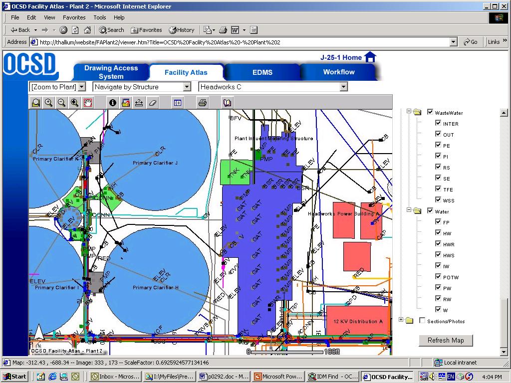
The Facility Atlas FA is a highly customized, web-based GIS map rendered through ArcIMS to over 200 OCSD staff users. The application data is stored in an Oracle database using ArcSDE software. The decision to develop this model in GIS instead of a CAD format was based largely on the ability of ArcSDE to allow data versioning, security and transactional roll-backs. These functions were identified as critical components for application maintenance or "change management."
Using GIS for the FA model created one major challenge. The source data for changes to this facility model were CAD drawings (both AutoCAD and MicroStation formats) used to design and build new facilities. Use of CAD format for engineering design work is a long-standing part of OCSD engineering workflow that could not be changed. To manage changes to the FA, OCSD would need to use complicated CAD drawings to update GIS features.
The need for detailed change management procedures was identified at the beginning of the Facility Atlas project. The first step in developing these procedures was to understand and map the historic engineering design workflow process. Next, new procedures and workflows were established to meet the goals of change management. From the new engineering workflow, new procedures, standards and data management tools were identified and developed.
The engineering design process consists of 29 major project milestones. Eight of these milestones affect the FA change management process.
Prior to the advent of the FA, design consultants would research hundreds of prior project drawings and create a basemap from which to base the design. An engineering design project began with a request for basemap data. Basemap data identified the current facility conditions (before the design) on which the design is based.
Several times during the design process, the incomplete engineering drawings are provided to OCSD staff for review. During this review, OCSD staff assesses the work completed for the purposes of progress payment, and evaluates the technical aspects of the design. At the completion of the design, final design drawings are provided. After the designed facilities are constructed, final "record drawings" are issued that vary from the planned design.
The new workflow was developed to ensure that new design data could easily be incorporated into the FA facility model. The new workflow was designed with the following constraints in mind:
· Minimize changes to existing workflow;
· Utilize existing OCSD staff and resources; and,
· Design work must be done in CAD.
The following changes were made to the existing engineering workflow to accommodate facility model maintenance.
At the beginning of a new engineering project, a copy of the current facility model was provided to design consultants and internal designers for use as a baseline model file. This was an advantage to engineering designers because it eliminated the costly facility research previously required. This change was an advantage, for two reasons, to the EDM staff who maintain the FA. First, it ensured that designers were working on accurate plant information which would make updating the FA easier. Second, it alerted the EDM staff to the existence of the new design project.
At engineering design submittal milestones the EDM group reviews engineering
drawings for compliance with EDM standards. These standards were developed as
part of the change management program to assist in FA maintenance. These standards
are discussed later in this document.
Many engineering projects can take five years or more to complete, and several can be underway at any given time. As a result, the basemap a design consultant begins work on may have changed radically by the time the project is complete. For this reason, the ability to "version" data is the cornerstone of the change management process. Data versioning allows EDM staff to save the basemap conditions at the start of a project. When the project is complete, edits to the Facility Model can be made to the "original conditions" basemap. The original basemap conditions data version can then be automatically reconciled using the ArcINFO geodatabase versioning tools.
At the beginning of a new design project, a new data version is created in ArcSDE. This version is called the "project" version. This data version is uniquely identified with the engineering project number that required the basemap data. When edits are made to a "project" version, a second "working" version is created. This is done to provide an additional level of quality control. This process is discussed further in a later section of this document.
The export procedure consists of saving the project version to a shape file. The shape file is imported into AutoCAD Map. To facilitate the process, OCSD developed standard AutoCAD templates that define layer names, layer colors and line styles and blocks names. The resulting AutoCAD file is then saved according to the standard naming convention and provided to the design consultant. The process involves out-of-the-box functionality with no custom applications required.
The file produced in the previous step is referred to as a Baseline Model File. This file represents the current condition of the facility at the time the project started. Design consultants are required to utilize a project model file, which contains project specific geometry such as pipe alignments, buildings, tanks, and other structural items. Combining these files along with a standard border produces a Composite Drawing. The OCSD CAD manual establishes the standards and guidelines governing the production of all CAD-related documents.
During the design process, drawings and their underlining CAD files are submitted to OCSD for review. This generally occurs at the 30%, 60%, 90% and final submittals. The CAD manager reviews both the hardcopy drawing and the CAD files for compliance to the OCSD CAD Manual. Special attention is placed on the project model files, as it is these files that contain the majority of information that will eventually be added to the FA. In addition to the CAD Manual, standard review templates have been created to promote uniformity and consistency. A recent addition to the review process is the AutoCAD Batch Standards Checker. This program will compare a file or group of files against a set of templates and report all non-complying items such as layer names, colors, etc.
Once the project has reached the construction or record drawing stage, the data is ready to be added to the FA. As mentioned previously, the facility contains utility information specific to the plants and does not include building interiors, structural components, or elevation information. Only project model files that contain planimetric information is incorporated into the FA. Within these remaining files are layers of information. Again only certain items will be added to the FA. These items are isolated using a variety of AutoCAD commands.
Once the map features have been isolated, they are attributed with information such as project number, system code, pipe size, material etc. Data attribution is completed in AutoCAD MAP using custom application software. The custom software routines provide input forms that constrain attribute data to lists of valid values. In this way, data integrity is enforced without the use of an object model. Guidelines and procedures for these processes have been documented in a series of operating procedures called the Maintenance Management Plan and are supported by the CAD Manual.
Map features are isolated onto layers that identify whether the features are additions, deletions, or modifications to the features currently presented in the FA at the data versioning point. One shape file is created for each of these types of data edit. The shape files are then viewed with the parent Facility Atlas data version and compared for accuracy. The map features are then loaded into the FA "working" version or added manually, depending on the type and complexity of the edits.
Following the addition of new map features to the "working" version, the edits are reviewed by the OCSD GIS administrator. When the administrator is satisfied the modifications made to the Facility Atlas are correct, the "working" version is reconciled and posted to the "project" version. The "project" version is then reconciled and posted to the production "default" version of the Facility Atlas.
Two types of conflict resolution are completed in the facility change management process. First, shape files created from the AutoCAD design drawings are compared to original basemap conditions. Any discrepancies between these conditions that are not a result of the engineering design process are noted and resolved with the design consultant or OCSD project manager.
The second type of conflict resolution occurs automatically when geodatabase versions are reconciled. Any problems resulting from this process will be identified in a conflict resolution dialog box presented by the geodatabase. These problems, most probably resulting from multiple edits to the same map feature, can be resolved with OCSD design staff, or through field verification of the disputed features.
The challenge of moving map features between the GIS and CAD platforms have been largely overcome with the solution presented in this paper. Although the solution takes advantage of many of the standard tools available in ArcSDE, ArcINFO and AutoCAD Map, the solution is largely procedural. Each step of the conversion process is governed by strict procedures. Each procedure is supported by documented standards. Many of the standards are enforced with procedures or custom software tools.
The authors would like to acknowledge the individuals who assisted in the development of this process: Steve DeWilde - OCSD, Martin Dix - OCSD, Dan Bunce - Brown and Caldwell. We would also like to thank Lee Johnston and Suzanne Timani of Esri for providing access to technical resources.
Orange County Sanitation District, 2002. Facility Atlas Maintenance Management Plan.
Marc Brown
Senior Data Management Specialist
Engineering Department
Orange County Sanitation District
PO Box 8127
Fountain Valley, CA 92728-8127
Phone: 714-593-7317
mabrown@ocsd.com
Marc Damikolas
Senior Engineer
Brown and Caldwell
16735 Von Karman Avenue
Suite 200
Irvine, CA 92606
Phone: 949-294-7435
mdamikolas@brwncald.com