Contingency Operations and the use of GeoBEST(Base Engineering Survey Tool)
Jeff Williams, Titan Systems Corporation
Introduction
GeoBEST, Base Engineering Survey Toolkit (BEST) is a stand-alone GIS application designed using Microsoft Visual Basic version 6.0 and ArcGIS 8.2 (Environmental Systems Research Institute, Redlands, CA). GeoBEST provides users with the ability to view the spatial extent of a selected location, estimate and then place the resources necessary to develop a deployed tent city GeoBEST uses Air Force and Army standards in deploying the correct amount of assets based on population and/or quantity of aircraft..
The deployment/bed-down planning operations were automated to provide planners a interactive, computer based tool for rapid development of base layout plans. The application allows the user to assign appropriate spatial locations to each of the facilities required at the identified base in response to a defined scenario. GeoBEST provides the deployment planning staff with tools to:
- Spatially visualize a layout plan for the facilities and equipment identified as part of any deployment scenario
- Interactively change the spatial plan based on users knowledge or concerns
- Interface with other modules that provide critical information and/or spatial configurations for facilities and equipment to be included in the layout plan
- Use standard regulations in regard to spacing requirements
GeoBEST provides faster response time in the development of base layout plans using established siting criteria and digital data sets. In addition, users can perform intelligent spatial placement of facilities to be situated on the site while still allowing the user to over-ride results provided. Based on input from the user, the software identifies the required components, which includes facilities and equipment, in response to a deployment scenario and defines rules for siting.
General Overview
From a GIS perspective, GeoBEST allows users to create a tent-city layout and store the information in a customized geodatabase for historical reference. These custom geodatabases are called scenarios. A user can either create a blank scenario or create a scenario that is established by population, deployment unit, or aircraft quantity. Once a scenario is established, tools are available for the user to add necessary spatial data for viewing purposes, placement tools for layout out of tent city, and analysis/reporting tools.
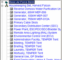
A key term within a scenario is deployment package units. Deployment package units categorize the type of assets (facilities, equipment, etc…) and establish population and existence requirements. Some deployment package units are required for every scenario, while others are based on population or other unit requirements.
Scenarios are stored in personal geodatabases(.mdb). They are similar to Microsoft Access databases but include a variety of tables and properties specific to ArcGIS. These personal geodatabases have been customized to store all information regarding a scenario. In this case, they are similar to ArcGIS map documents where the document stores all layers, graphics, tables and properties internally. This is the same case for scenarios. All work done within a scenario is saved to a custom personal geodatabase. The file can be re-opened at any time to continue their work.
At the beginning, creating scenarios may seem slow and trivial. Needless to say, but laying out 100 temper tents, associated air conditioning units, utility cables, etc… could take some time. However, GeoBEST has been designed to facilitate a growing awareness of existing scenarios. This means that with each scenario created, users have the ability to select all or some assets and store then as templates. When the need arises to lay down multiple assets in a pre-configured manner, the user only needs to insert the template, which alleviates the tedious task of laying out hundreds of assets.
Interface
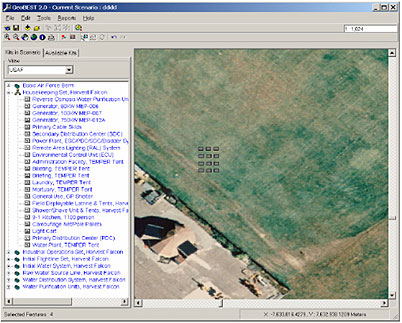
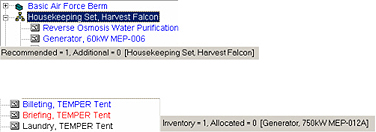
The interface is separated into a Table of Contents and Map window. The Table of Contents provides a tree view that displays deployment package units estimated and additional units available for use within the Scenario.
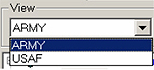
The service view allows users to toggle between services to lay out components associated with each. The Service view will display multiple services if a joint mission was developed through the planning wizard. If not, a single service will be displayed in this drop down menu. When a service is selected, kits and components associated to this service will appear in the Table of Contents.
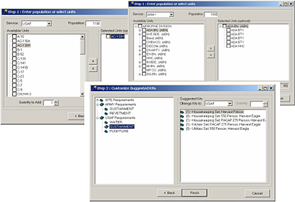
Scenario Building Process
The scenario building process is a three step approach. First, users define the general scenario properties concerning the name, default service, and location. Next, they define the required units if the scenario pertains to Army or in the case of the Air Force the estimated population or quantity of aircraft. When using aircraft, the software will estimate the population. Finally, the software will estimate the deployment package units viable to the estimated population. These kits are optional and can be tailored to fit requirements.
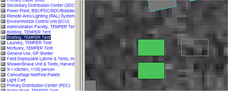
Drawing components
To place a component or asset within GeoBEST it's just a matter of selecting the component. GeoBEST will establish the dimensions of the component and when the mouse is dragged over the spatial data, users will see an outline figure of the extent of this component. By single clicking on the display, the component will be drawn at scale.
Users are able to move, rotate, copy, paste and delete components whenever necessary. Inherent within GeoBest is the ability to undo and redo changes.
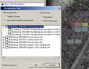
Analysis
Various tools have been developed to analyze the tent city based on military regulations. For instance, the Air Force has guidelines for the separation distances for temporary facilities in a dispersed or non-dispersed fashion based on threat, mission, etc… With each combination of a facility or group, there are different standards that must be met. For instance, a billeting tent to another billeting tent requires a 12 ft stand off distance. The constraints analysis tool provides graphics that allow users to understand the distance requirements as noted in the standards.
In addition to the constraints analysis tool, there are tools for reporting required labor, utility, and power requirements. There are also tools that will establish an estimated quantity of facilities that can accommodate a digitized area.
Summary
In conclusion, these types of military applications have been technology advancements to many decade or older processes that have a geospatial context. Titan Systems has played a large role in developing COTS solutions that integrate the use of GIS into everyday military tasks.
![]()
Titan Systems Corporation
1501 Merchants way
Niceville, FL 32578
http://www.titan.com
Tel: 850 897-5380