Data Integrity and Validation for Enterprise-Wide Esri Implementations
Philip Penn, SchlumbergerSema
In the course of implementing a large Arc8 project, SchlumbergerSema encountered data integrity and validation issues that were not solved by Esri's built-in capabilities.This paper will review the data integrity and validation concerns that are critical in large (hundreds of users) Arc8 implementations and present the solution developed by SchlumbergerSema.
Data integrity is an established concept in the RDBMS world. Data types & constraints are part of the schema and enforce a certain level of correctness in the database.Validity is enforced by the RDBMS and users cannot enter data that will leave a potentially corrupt database.
The requirement for Data Integrity & Validation stems from 2 basic needs
To assess accuracy of data provided by data vendors
- To maintain quality of data entered by users on a daily basis
RDBMS constraints can only go so far, and are typically limited to existence (null checks), relationships and primitive value ranges. In a GIS, constraints can also be of a spatial nature - connectivity, for example. Domain constraints, more commonly known as business rules, may be more complex and not possible to store in a database.
FIGURE 1 - RULES MANAGEMENT
ArcInfo provides functionality for validation and connectivity through open (user-defined) and closed (system-defined) methods. The closed methods include specifying connectivity through UML, defining Domains for attributes and a validation tool.Versioning is also part of the validation workflow in a multi-user editing environment, as it allows many changes to be submitted at once.The open methods include implementing interfaces IValidate and IValidation, so that custom business rules can be called when ArcInfo is about to commit a record.
Given that ArcInfo includes this combination of flexibility (interfaces) and foundation (tools), why was it necessary to write a paper on validation and integrity?
Although Arc8 is a significant improvement on previous versions of ArcInfo with respect to object validation, its capabilities fell short of what was required for an Enterprise-wide project conducted by SchlumbergerSema.
The default implementation of validation had shortcomings pertaining to the flexibility of inputs & quality of the output. Also, the concept of validation in Arc8 is that it is optional.This is akin to optionally dropping constraints upon a CRUD operation in an RDBMS - almost unthinkable.
Furthermore, because it is specified at the subtype only, the connectivity model in Arc8 was found to be too specific to be easily used. In particular, the UML model grows too large to be compiled and the lack of specifying rules rather than exceptions left the exercise as too error-prone.
The bridging of these gaps provides for the basis of this paper. In each section below the Esri functionality shortfall is described and the solution developed is presented.
The experiences cited are primarily from a project for a city government, including a multi-user editing solution on ArcInfo 8.1.
All validation rules in the Geodatabase are effectively treated as warnings rather than errors.There is no way to specify that a given rule must be conformed to before data can be published/posted to the Default version for general use.
Esri has not implemented a mechanism to provide Class level validation rules.For example, it is not possible to specify a uniqueness constraint as an Esri rule.
The Geodatabase validation function supplied with ArcMap is inadequate.For a set of selected features, the native function executes all the rules associated with each feature on a feature-by-feature basis. When a validation failure is encountered, the function stops validating that feature and begins validating the next feature.When all features have been validated in this way, the function displays a simple message box indicating how many features failed validation. It does not indicate which features failed or the reason for failure.
Esri has not provided a COM interface specification or consistent framework for defining custom validation rules.This means that Esri rules and custom rules cannot be managed or treated in the same way.
The data integrity strategy for the Geodatabase can be characterized as follows:
� Data validation is not an optional activity.
� Validation may be invoked in four ways
- "In-line" automatically during record entry
- On a single record
- On a selected set of records
- For all edits before posting the edit version
� The user may edit data only in a Geodatabase version; the user may not edit the sde.Default version.
� Pre-post validation checks are executed automatically.Data may not be posted if any records in the version are in violation of a mandatory rule.
� Validation runs from start to finish; it validates every rule on every selected row - it does not stop at the first validation failure.
� Validation failures are clearly presented with the reason for each violation. Custom tools enable the user to efficiently correct the data.
� Custom rules are developed using an architecture similar to the Esri Geodatabase rules.
- Each custom rule is developed as a COM component.
- Custom rules may be associated with Class, Subtype, and Field.
� Custom rules may be reused by many fields, and so forth.
� Custom rules carry a property of Severity with possible values of Error or Warning.
� All Esri rules are treated as mandatory rules, that is, a Severity of Error.
� Custom rules are associated with classes through a configuration table.
� The custom rules framework supports the development of all Esri optional validation interfaces.
� Esri connectivity rules are used judiciously and augmented with custom rules for maintainability.
This strategy is implemented by two related parts: in the definition of Custom validation rules and through the validation mechanisms that invoke those rules.
Data validation requirements are defined in the following use case specifications:
� Validate set
� Manage session validation rules
� Pre-post validate
� Manage validation rule exceptions
With the strategy outlined above in mind, a Custom Validation architecture was designed, being split up into three tiers - data transfer, business logic and user interface.The goal was to make each tier independent of the others so that it could be reused.
FIGURE 2 � CUSTOM VALIDATION COMPONENTS
At the core of the Validation framework lays ICustomValidation, which returns a collection of IValidationError instances.
FIGURE 3 - CUSTOM VALIDATION INTERFACES
Custom Rules are read from the database when the ClassExtension::Init routine is called.
FIGURE 4 - VALIDATIONERROR INTERFACE
The IValidationError class contains detailed information concerning the broken rule.
The validation tool in Esri was seen as too simplistic as to be useful. Specifically it was
- Optional
- Returns only one error message at a time
- Multiple features yield a generic message
- Highlights features in error
The above-described validation architecture describes the mechanisms by which data integrity is maintained using the custom validation engine. For this engine to be useful to users, however, an intuitive user interface was developed.This interface was designed to display the validation results to the user and provide custom functionality to allow the user to edit data and correct any errors the data may contain. Various standard editing aides and custom object management functionality were built onto this interface.
This new user interface, shown below, gives a completely new look to the standard Esri validation functionality and provides useful feedback to the user when validation rules are broken. Unlike the Esri validation architecture, which only displays the number of records with errors, this interface supplies the user with all errors that occurred for all features or objects validated.This is displayed in a tree view for easy navigation.
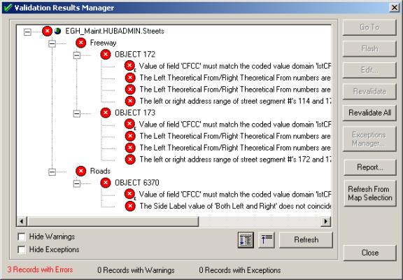
FIGURE 5 � VALIDATION MANAGER USER INTERFACE
The rules manager served two purposes
- To display the rules loaded by feature, subdivided into rule type
- To allow the user to selectively apply rules by unchecking the rule concerned
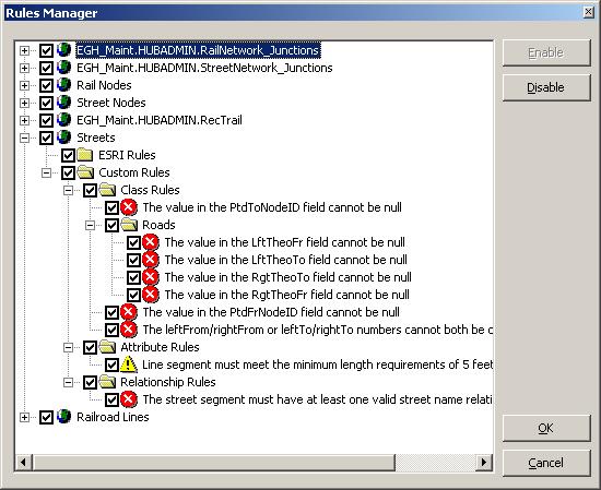
FIGURE 6 � RULES MANAGER
For a given object, its broken rules can be selectively ignored at CustomPost time through the Exceptions Manager.This provides the user with the opportunity to mark each broken rule as an exception.
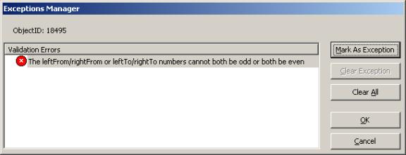
FIGURE 7 � EXCEPTIONS MANAGER
Arc8 implements connectivity using a geometric network feature class.The geometric network specifies the set of feature classes that can connect. By default, all feature classes in a geometric network are allowed to connect to one another.By specifying connectivity rules, the connectivity model implemented in the geometric network can be constrained.
Connectivity rule definitions are based on subtypes. One unfortunate characteristic of the Esri Geodatabase is that as soon as one connectivity rule is needed, all possible connectivity rules must be specified in a geometric network. For example, a simple sewer geometric network has three feature classes: sewers, laterals, and junctions. The sewer subtypes are main, pressure main, and inlet lead. The lateral subtypes are laterals and connections.The junction subtypes are valve, manhole, fitting, vault, lift station, and treatment plant. If no connectivity rules are specified, all feature classes can connect to one another, including invalid combinations such as a connection to a main.Arc8 does not allow connectivity exceptions to be specified.As a result, to identify this constraint, Arc8 requires that all legal combinations be specified and the connectivity combinations that are not valid be omitted.In this case, 60 combinations are possible (15 edge-to-edge connectivity rules and 35 edge-to-junction connectivity rules).Implementing this simple sewer network example with one constraint requires specifying 59 connectivity rules.
This example illustrates the inherent problems in solely using Arc8�s connectivity rules to implement a connectivity model, especially when there are relatively few constraints.The project sewer data model had 15 feature classes with a total of 160 subtypes, which creates a maximum of 5,740 connectivity rules (861 edge-to-edge connectivity rules and 4, 879 edge-to-junction connectivity rules). Because it is difficult to implement or maintain a large number of connectivity rules, SchlumbergerSema changed its design strategy.
The first part of the new design strategy reconfigured the sewer data model to minimize the number of subtypes, and by extension, the number of possible connectivity rules.If used at all, Esri connectivity rules are used only to control the most general connectivity.In this context, general connectivity rules are rules that manage connectivity between feature classes and subtypes only.In the new sewer data model there are 15 feature classes with a total of 15 subtypes. Twenty Esri connectivity rules have been identified that will implement a general connectivity model.
The second part of the new design strategy implements additional connectivity constraints as custom software. One example of a custom connectivity rule is enforcing proper connectivity based on usage; that is, sewer can connect to sewer or combined and storm can connect to storm or combined, but sewer and storm cannot connect directly to one another. SchlumbergerSema considered two options for implementing the custom connectivity rules:
Adding or linking the custom connectivity rule to the Esri-generated connectivity rules
Implementing the custom connectivity rule using the standard framework being implemented in all applications
The major consideration in the implementation approach was Esri�s recommendation for administering a geometric network.Esri recommends that geometric networks be dropped and rebuilt routinely as part of the Geodatabase administration.This deletes and rebuilds all Esri-generated connectivity rules.If custom connectivity rules are linked or added to the Esri-generated connectivity rules, the custom connectivity rules have to be re-added or re-linked every time the geometric network is rebuilt.Since the standard framework SchlumbergerSema was implementing for the applications was integrated with Esri�s standard validation framework and was not affected by rebuilding the geometric network, this approach was chosen for implementing the custom connectivity rules.Using the example above, the usage connectivity constraint is implemented as two custom connectivity rules.These two rules are associated with each feature class in the sewer model and are automatically invoked any time a sewer feature class is validated. One rule checks edge to junction connectivity, and the other checks junction to edge connectivity.The CustomConnectRules configuration table drives these two rules. This table includes two columns: From_FeatureType and To_FeatureType. This table contains all valid from and to connections for all feature types in all feature classes in the sewer network.
The usage example from above illustrates these two rules. Starting with two line segments connected by a junction, the first line segment is a sewer main, the second is a combined main, and the junction is a combined manhole. The connectivity between these features is checked in two steps. The first check is between the first line segment and the junction.The configuration table is queried to see if this connection pair has a matching pair in the table (From_FeatureType = Sewer Main and To_FeatureType = Combined Manhole).The second check is between the junction and the second line segment. Again, the configuration table is queried for the connection pair (From_FeatureType = Combined Manhole and To_FeatureType = Combined Main). If the connection is found in the configuration table, the connection is valid. Otherwise, the rule returns an error, and the connection is invalid.This method for validating connectivity removes the need to create thousands of individual connectivity rules.This method is also extremely flexible when adding or removing valid connection pairs. The change only needs to be made to the database configuration table and takes effect immediately upon modifying the table.
To summarize, the connectivity implementation strategy devised was to use a combination of Esri connectivity rules and custom connectivity rules.The data model is structured to minimize the number of subtypes, and the Esri connectivity rules, if needed, are used only to implement general connectivity.Custom connectivity rules are used to add constraints to the connectivity model.
SchlumbergerSema recommends this strategy for its ease of implementation, ease of maintenance, and scalability. The low number of connectivity rules (Esri and custom) simplifies implementation and maintenance.This strategy is highly scalable since additional fidelity in the connectivity model can be added easily with additional connectivity rules. For example, in the future, size connectivity constraints can be easily added (things connecting must have matching sizes) and material connectivity constraints (things connecting must have compatible materials) by implementing a single custom connectivity rule for each constraint and then associating the connectivity rule to the sewer feature classes.
In Arc8 the IRow has an IValidate interface.Constraints of IValidate included:-
- Validate: returns only one message
- GetInvalidRulesByField: returns field rules that were broken (known Bug in Esri � fails every time)
- GetInvalidRules: returns row rules that were broken (known Bug in Esri � fails on connection rules)
Given that the project concerned did not use C++ (and therefore Custom Features were not an option), an interface was created to wrap the IRow interface.This allowed for custom property behavior (as well as a more intuitive programming interface for accessing property values on a row).
FIGURE 8 � ROWATTRIBUTES INTERFACE
The PerformFieldValidation property enables exceptions to be thrown if a field value breaks any rules. This is a finer level of granularity than the Validate method because it means that an error can be discovered as soon as the object becomes invalid (rather than waiting to validate the whole object). This is similar in functionality to the IObjectClassExtension interface, but with richer error reporting.
The main consumer of RowAttributes is the RowAttributesGrid, which is used universally in the application to supplant the existing editor by implementing the ObjectInspector interface.
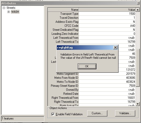
FIGURE 9 ATTRIBUTES EDITOR
Figure 9 shows the RowAttributesGrid in association with the Field and (Row) validation checked. The message box displayed has arisen because an error was raised when the user set an invalid field.
The three key points in this paper are:
- Does not force the user to enter valid data as an RDBMS would
- Validation tools are too primitive to be useful
- The connectivity rules are unworkable due to complexity of the growing UML model
- Database tables for storing rules defined in COM scripts
- Rich validation information
- User interface for displaying validation information
- The ability to selectively apply rules and mark exceptions
- Integrates with Esri validation framework
- Custom Posting Validation
- RowAttributes grid
- Programmatically through ICustomValidate
The framework produced was proven to be reusable across projects.
Philip Penn
Software Engineer
SchlumbergerSema
6399 S. Fiddlers Green Circle, Suite 600
Greenwood Village, CO 80111
Phone:(303) 741-8400
Fax:(303) 741-8401
The author thanks Kelly Goldin, Shannon Holck, Graham Morgan, Tom Lonski, Joel Tharp and Matt McFarland for their input.