Developing Custom ArcMap Symbology
Using Group Layers and Style Files
Geoffrey Baldwin, Mark Dodich
Abstract:
A very powerful feature of ArcMap is the ability to maintain cartographic
standards through the development of custom symbology. The advent of ArcGIS 8.x
brings new capabilities to map production by introducing features that every
user needs to become familiar with: Group Layers and Style Files. This paper
discusses how group layer files are utilized to create custom map symbology so
that maps of any scale are automatically rendered with the appropriate feature
symbology. This paper also addresses how style files are created and implemented.
AAA�s new TourBook � map production methodology will be described to illustrate how these
techniques have been successfully implemented.
Introduction
AAA (the American Automobile
Association) has offered high-quality travel-related services, road safety
education, financial services, and a variety of products to the traveling
public for more than one hundred years. Today AAA serves its more than
forty-five million members in 1,123 offices throughout the US and Canada. At
the core of AAA�s travel-related services are a variety of map publications ranging
in scale from highly detailed city maps to regional maps used for travel
planning. In addition, AAA produces 24
TourBook � guides that contain more than 600 maps providing
detailed information on attractions, lodgings and restaurants throughout North
America. For the 2001 edition, AAA
published more than 28 million TourBook � guides.
The focus of this paper
describes the migration of our TourBook � maps into
the GIS. It also addresses, more specifically, how AAA has developed efficient
cartographic production methods and implemented map series symbology using
ArcGIS 8.x.
AAA�s GIS database and the transition to ArcGIS
AAA�s GIS was initially
developed on the Unix ArcInfo 7.x platform using SDE for Informix. The goal was
to build an intelligent, enterprise-wide GIS system using a seamless nationwide
master database. This database would support both paper-based map production
and electronic travel related products.
Currently, AAA manages its
GIS master database with Esri�s ArcSDE 8.x for Oracle. In addition to the
master database, individual cartographic "product layers" are also stored in
ArcSDE. With ArcSDE, we can either
cascade real world changes from the master database directly to any product
layer, or make product only cartographic changes to fit specific customer
requests. Although the UNIX ArcInfo 7.x
platform has allowed us to migrate our City, Vicinity and State map product
lines successfully to a GIS environment, AAA is continually looking at how it
uses GIS to improve efficiency in both database development and map production.
When Esri first developed
ArcGIS technology AAA welcomed the opportunity to be a beta site for Esri. The
goal was to investigate the new applications and to find out how they could
enhance AAA�s map production process. Some of our early efforts were not very successful as the software was
in the early stages of development. The 8.1 release of ArcGIS allowed AAA to
move forward with testing the migration of the TourBook � map production system
to that platform. The advantages of
this approach were:
The new desktop tools had out-of-the-box functionality requiring little customization for map production
ArcGIS required less training because of the users familiarity with Microsoft Windows applications
Performance issues were minimized with the smaller data sets used in TourBook � maps
Testing the ArcGIS environment provided a good comparison with our sheet map production efforts using UNIX ArcInfo 7.x
TourBook � map production with ArcGIS
One major issue we had to
address was generalization, or the need to extract different map features from
the master database for TourBook � maps at various
scales. We decided to modify the AML extraction
code that was already in place for sheet map products. While we recognized
ArcMap's ability to constrain feature visibility through the use of SQL expressions,
the business decision was made to
use a proven and established method for the initial data extraction. For more information on AAA�s generalization
techniques, please refer to the reference section of this paper.
As an overview, here are the
steps that were required to develop the TourBook � map
production system on ArcGIS 8.x:
Evaluate map specification requirements
Create feature extraction query logic for each map type and scale
Build group layer files to store feature symbology for each pre-determined scale group
Create a style file to store our standard map annotation styles
Train staff using desktop ArcGIS, specifically ArcMap edit tools
Create TourBook � prototype maps and develop production procedures
Test the ArcMap output to ensure it meets printing standards
Group Layers and TourBook � Map Specifications
In ArcGIS, geographic
information is displayed in ArcMap as layers. Each layer represents a category
of features such as highways, drainage or points of interest and includes the
symbology, display, labeling and query information. Group layers are a combination of layers that are represented as
a single entry in the table of contents in ArcMap.
Before the process of
building group layers can begin, map specifications have to be carefully
developed. One of the first tasks in
creating TourBook � map specifications is to
determine the requirements by closely evaluating the different types of
maps. Below is a set of diagrams which
represent a small sample of the different maps that are presented in the AAA TourBook �
Figure 1.1 - 1.6: Examples of TourBook � maps
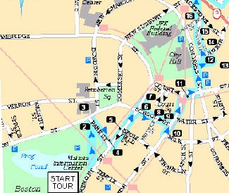
Figure 1.1:
Boston - Freedom Trail Walking Tour
This large-scale map
contains AAA approved points of interest based on a specific route described
in the TourBook � guide text.
|
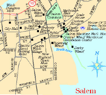
Figure 1.2: Salem Attraction Map
This attraction map
features AAA approved points of interest in relation to roads, parks,
airports and other landmarks.
|
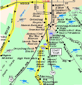
Figure 1.3: Gettysburg National Military
Park Map
This map shows points of interest and natural or historic
features in and around the national park. This map also contains a suggested
driving tour indicated by a yellow highlight.
|
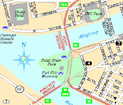
Figure 1.4: Downtown Pittsburgh Spotting
Map
This Spotting map shows AAA approved lodgings and
restaurants in relation to roads and other landmark features.
|
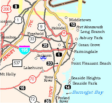
Figure 1.5: New Jersey Orientation Map
This Orientation map
features towns that have AAA approved points of interest. Recreation areas are
also included and referenced in a detailed chart that describes available
activities at each site.
|
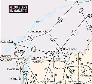
Figure 1.6: Maine-New Hampshire and Vermont Driving Distance Map
This Driving Distance map contains trip-distance and driving-time information for travel planning.
|
These diagrams demonstrate
the variety of features that need to be considered for each map type.
Large-scale maps such as the Boston-Freedom Trail Walking Tour map in Figure 1.1
and the Downtown Pittsburgh Spotting map in figure 1.4 feature detailed
building footprints and cased roads. Small-scale maps such as the New Jersey Orientation map in Figure 1.5
feature a highly generalized road network. For the Driving Distance Map in figure 1.6, the straight lines between
towns clearly indicate that the purpose of the map focuses on trip planning.
Scale Ranges
The process of evaluating
scale ranges is not only a key factor in how specifications are built, but also
provides a solid foundation for creating extraction logic. Figure 2
demonstrates the relationship of the TourBook � map types
described in figures 1.1-1.6 to the 14 different scale ranges that we developed
for the AAA GIS. The scales are
indicated by numbers ranging from the largest scale (1) to the smallest scale
(14). For example, scale level 1
represents any map with a scale greater than 1:15,000; scale level 4 is any map
between 1: 50,000 and 1:125,000, and scale level 14 is any map with a scale
smaller than 1:7,600,000.
Figure 2: TourBook � maps and
scale ranges

Understanding the
relationship between map type and scale is the most important factor in
building map specifications and eventually determining how the Group Layers in
ArcMap are organized. While TourBook � maps vary greatly in content, we determined that the
best approach was to evaluate our specifications according to scale. Road classification is an excellent example
of this concept.
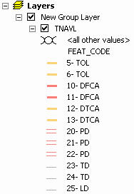
In the AAA GIS, roads are
classified based on the attribute "FEAT_CODE". The FEAT_CODE is both a physical and
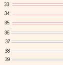
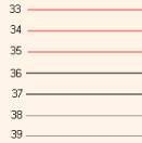
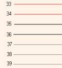
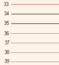
functional characteristic of a road feature. Figure 3 below contains FEAT_CODES 33-39, which are classified as paved
undivided roads. FEAT_CODES 33-35
generally have primary arterial functionality and represent roads that connect
cities, or roads that allow for a high volume of traffic. FEAT_CODES 36-39 generally have secondary
arterial functionality and most likely would be roads that connect between
neighborhoods, allowing for moderate volumes of traffic.
As you can see in Figure 3,
as the map scale gets smaller, the criteria for a road to reach secondary or
primary level becomes more stringent.
Figure 3: Road Classification system cross-section - FEAT_CODES 33-39
|
|
|
|
|
Scale
Level 1,2
For the
largest scale maps, all
roads including undivided roads are represented as double lined or cased road
features.
|
Scale
Level 3,4
For
large-scale maps undivided roads are represented with single line symbology. There is no drop in functionality as these
roads are very important at these scales.
|
Scale
Level 5,6
At the
medium scale level there is less primary functionality as these roads have
less importance. Some of the roads
will get filtered during automated extraction at these scales.
|
Scale Level 7-13
At the
smallest scales these roads have significantly less importance. Many, if not
all of the roads will get filtered at these scales.
|
After a thorough review of
our existing TourBook � map specifications, we found
that many area, line and point features such as parks, lakes, railroads and
points of interest had the same symbology despite great differences in scale.
However, when we considered road symbology, it became clear that the importance of the
feature (Red for primary, black for secondary, gray for local) was dependent on
the scale of the map and, therefore, would determine how many group
layer files we had to build.
In the section titled Creating
Symbology and Applying Group Layers, there will be more detail of how
group layers store display properties and how they can be effectively utilized
in ArcMap for production cartography.
Style Files and TourBook � Map Specifications
In ArcMap, specific
information about the properties and characteristics of text, symbols,
and other map elements can be stored in a Style file. In the TourBook � production environment we have successfully used a
customized style to communicate to production staff which graphic elements are available and how
they should be applied.
By using the Style Manager
in ArcMap, the AAA TourBook � style file was
created containing all of the markers, lines, fills and text that are applied
as graphics and/or annotations on our TourBook � maps. Through the use of the Style Manager dialog
box, we found that symbols and map elements were easily created and
modified. All of this work was done
without any customization to ArcMap, and unlike the marker edit commands in ArcInfo 7.x, was
very simple to put in place and update.
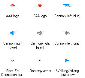
Figure 4: Examples of the symbols created for
AAA TourBook �
maps
|
TourBook � Style Files
|
|
|
|
|
Markers
The
symbols in this marker style are not master database features and are only
applied graphically as needed to the map document or annotation layer.
|
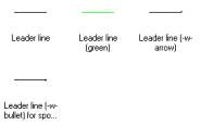
Lines
Leader
lines are added to the map document for use with text or symbols as
needed. A spec sheet provides
instructions for the proper application.
|
Highway
Shields
By using
this custom style the user selects the appropriate shield and populates the
number. There is also a smaller shield available as an alternative.
|
The greatest difficulty in
creating the AAA TourBook � Style file was the
inadequate quality of the symbols that were imported. There was some initial success
importing markers from our UNIX ArcInfo 7.x symbolsets; however, the quality
was not acceptable (pixilated, fuzzy images). A similar experience occurred
when testing symbology from a Microstation cell library and Adobe Illustrator
software. While these efforts have been
largely unsuccessful, Esri continues to improve how symbols can be converted
for use in the ArcGIS environment.
Included with the latest
delivery of ArcGIS 8.2 is an ArcInfo 7.x symbol conversion utility. While we
have not had time to fully test the program, after some initial efforts we
found some limitations. Esri states in the on-line documentation "The
program is not intended for use with symbolsets that utilize patterns from IGL,
Intellifont or Postscript fonts". Since all of our UNIX ArcInfo 7.x markersets are IGL and all of our text
fonts were developed using Intellifont, it appears that this symbol conversion
program will not meet most of our needs. Because there are few options in ArcInfo 7.x, most Esri customers using
either IGL for markersets or Intellifont to develop text fonts will discover
the same limitation. For more information on this topic, see the Reference
section at the end of this paper.
Fontographer: Third-party font-creation software
As Esri suggests in the
ArcGIS documentation, precise TrueType fonts can be created using third-party
font-creation software. After an
evaluation of different software we decided that Macromedia�s Fontographer
best fit our needs. The software allows the user to easily create fonts containing
characters that can be used in an ArcGIS group layer or style file. In
addition, we found that many of our pre-existing ArcInfo 7.x symbols could be
easily recreated by bringing them into Fontographer as a backdrop, and then
re-digitizing them as new font characters.
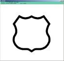
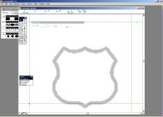
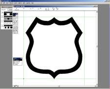
Figure 5 is an example of
the process used to import a U.S. highway shield from a UNIX ArcInfo 7.x
markerset and recreate it as a TrueType character for use within a style file.
Figure 5: Process of creating TrueType characters in Fontographer
|
|
|
|
Step 1
UNIX ArcInfo 7.x marker symbol is captured in a
screen copy
|
Step 2
The screen copy is brought into Fontographer as a
background image.
|
Step 3
The shape is digitized using the precise set of
tools available in Fontographer.
|
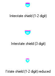
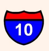
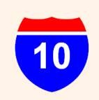
Although Highway shields are
readily available in the Esri symbol set, from a cartographic perspective we
wanted to retain the "look and feel" that our members are accustomed to. Figure
6 demonstrates two examples of the difference between default Esri symbology
and what was built for the AAA TourBook � production
system using Fontographer:
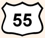
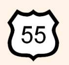
Figure 6: Comparison of Esri symbology to custom symbology
created using Fontographer
|
|
|
|
|
Esri
Symbology
The heavy
black line is inconsistent with how Federal Interstate shields are
symbolized. This generic shield is used for one, two and three digit shields.
|
AAA Custom Symbology
This
symbol matches the Federal standard for Interstate shields in both shape and
color. The symbol is enlarged to accommodate three digits.
|
Esri Symbology
This
generic U.S. Highway shield is the same width for one, two and three digit
shields.
|
AAA Custom Symbology
By
customizing the size, the two-digit U.S. Highway shield is more aesthetically
pleasing and takes up less space in crowded map areas.
|
Creating Symbology and Applying Group Layers
There are many ways to
create custom symbology in ArcMap. One
effective method is to bring sample data layers into ArcMap so that new
symbology can be evaluated at the appropriate scale. To begin, a directory is added in ArcCatalog and all the data
layers that require custom symbology are copied into the directory. In this example a road layer from the sample
data will be added in ArcMap. The road
layer initially draws using default ArcMap single line symbology at a specified
scale. By opening up the properties of
the road layer, the draw symbology can be changed from the default to unique
symbols based on the values found in a column of the attribute table. In this case, the AAA TourBook � road layer will be drawn based on the FEAT_CODE
attribute.
Figure 7: Using the Layer Properties dialog box to set draw
symbology to an attribute

By selecting each symbol individually,
the properties can be customized. As an
example, by double-clicking on the light green line next to FEAT_CODE 33 above,
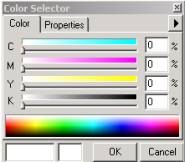
the Symbol Selector dialog box opens. By clicking on the Properties
within the Symbol Selector box, the Symbol Property Editor is
opened, and the symbol is ready to be edited. The symbol that we will create
using FEAT_CODE 33 is a primary divided road that is represented as two red
casings with a white fill in the center. Figure 8.1- 8.3 demonstrate the steps that are required to create this
symbol.
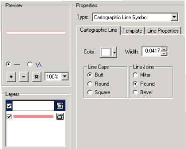
Figure 8.1: The initial steps involved to create custom
symbology
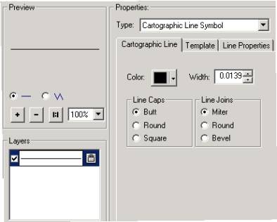
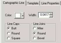
Step 1: The symbol property edit box is opened. The type
of feature is already set as a Cartographic Line Symbol. ArcMap assigns the
line a default color and width. By changing
these settings the draw symbology can be customized.
|
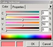
Step 2: The color is easily changed to the desired
specifications.
|
Step 3: In this example the width is set to inches. The
Line Caps and Line Joins are set as shown above. We found this to be the
optimal setting for all line symbols.
|
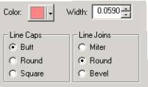
Figure 8.2: Steps required to add a second line symbol
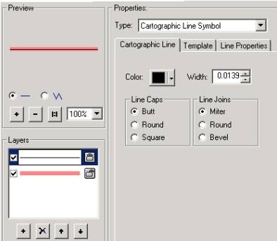
Step 4: A line is added and elevated so that it draws on
top of the red symbol already created. The color and width are based on
default settings.
|
<
Step 5: The color is changed so that it prints with a
white fill.
|
Step 6: The width is set smaller than the red line
symbol, creating a thin red lined casing with a specific width on either
side.
|
Figure 8.3: Finishing the symbology and creating a group layer
 Step 7: The symbology is complete. Once this process is
finished for all of the different types of road features, the initial group
layer is ready to be created.
Step 7: The symbology is complete. Once this process is
finished for all of the different types of road features, the initial group
layer is ready to be created.
|
 Step 8: In the ArcMap table of contents, right click on
Layers, and select "New Group Layer". Drag the road layer into the new group
layer. Right click on the New Group Layer and save the group layer file.
Step 8: In the ArcMap table of contents, right click on
Layers, and select "New Group Layer". Drag the road layer into the new group
layer. Right click on the New Group Layer and save the group layer file.
|
The group layer file that is
generated as a result of Step 8 is the first step in creating the new group
layer. The procedure is very similar for area fills, except that the property
type we typically use is the "Simple Fill Symbol". Regarding marker symbols, we
found that it is advantageous to build a TrueType font file using third party
font creation software as described in the previous section, then use the
"Character Marker Symbol" option in ArcMap.
All map layers should have
be added to the group layer and saved to the group layer file. After all the
layers have been customized, the final step is to delete or move the sample
data to a different directory. By doing this, the link is broken between the
group layer files created in step 8 and the data. This is a necessary step
because the new group layer file must not be associated to any single data set
before it is brought into ArcMap for the creation of a new map.
Applying Group Layers
In the ArcGIS help dialog,
Esri provides an example of why group layers are helpful in ArcMap: Suppose
you have two layers on a map representing railroads and highways. You might
choose to group these layers together and name the resulting layer
"transportation networks". We chose to think about group layers
differently as we learned more about how they could be applied.� It was envisioned that every TourBook � � group layer would contain all the individual layers
necessary to create a complete map. The advantage in using this method is that
up-to-date feature symbology can easily be applied to a map in the form of a
single, new group layer.
Based on some of the
principles that were established in the Group Layers and TourBook � Map Specifications section, the group layers were created for the TourBook � production system based
on scale. Here are the five unique group
layers that we developed to symbolize the TourBook � data:
Final_1-2.lyr
- Group Layer for maps
with a scale larger than 1:25,000
Group layer for maps
with a scale between 1:25,000 and 1:125,000
Final_5-6.lyr
- Group layer for maps with
a scale between 1:125,000 and 1:300,000
Final_7+.lyr -
Group layer for maps with
a scale above 1:300,000
To apply a group layer in
ArcMap, the layer file is added using the same procedure as any other data
set. In this example we are going to
symbolize TourBook � data for the Philadelphia
downtown map. Since the map scale is
greater than 1:25,000, we chose to bring in the Final_1-2 layer:
Figure 9.1: Adding the group layer to the blank map document in
ArcMap
 Step 1: Starting with a blank map document, hit the add
data button and find the directory where the group layer is stored (see
step 8 in Figure #8).The links to
the data will be broken, and a spatial reference message will appear. This is
expected because in the next step we will be associating this group layer to
a specific data set. Click OK and
continue.
Step 1: Starting with a blank map document, hit the add
data button and find the directory where the group layer is stored (see
step 8 in Figure #8).The links to
the data will be broken, and a spatial reference message will appear. This is
expected because in the next step we will be associating this group layer to
a specific data set. Click OK and
continue.
|
Figure 9.2: Linking the Group layer to specific map layers

Step 2: Select any of the layers in the table of contents
and click on the red exclamation point to set the data source path to the
location of the map data. In this
case we found the 2180 directory where the Philadelphia downtown map data is
stored. The next step is to select
the corresponding data layer, in this example tnavl.shp. Once the Add button
is selected all of the layers in the group will be automatically linked,
provided that the name of the data layers match those in the group layer. If
the names are different, they will have to be resolved individually to create
a link between the individual layers and the data.
|
Figure 9.3: Drawing the map data according to standards set by
group layer properties

Step 3: Right click on any of the layers and select Zoom to
Layer. The data will draw according to the specifications contained in the
group layer (in this example we zoomed in further in order to clearly display
the symbology). At this point the .mxd can be saved (generally in the
directory where the data is stored), and the editing process can begin.
|
This simple explanation of
how to apply group layers in ArcMap is only one example of how powerful the
group layer concept is. Not only can a
group layer provide the draw symbology, it can also store the appropriate draw
order and all of the labeling properties for each layer. In addition, layers also
have the ability to display a subset of features in a layer using a definition
query. These properties can be stored in the group layer file as well. All of these very powerful tools are
described in Figures 10.1-10.6:
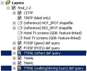
Figure 10.1 : How ArcMap utilizes the table of contents to determine
draw order
|
|
Figure 10.2 : A Subset of features requiring a draw order that is on
top of the road network
|
|
|
|
|
ArcMap draws each layer
based on the order in the table of contents, drawing the bottom layer first.
The two layers that are highlighted each point to the same data source. They
both contain different sets of features that require two different draw
orders.
|
|
The features contained in
this layer will be drawn after the two road layers (TAAAL, TNAVL), as these
symbols need to print on top of road features.
|
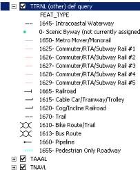
Figure 10.3 A different set of features requiring a draw order that is below
the road network
|
|
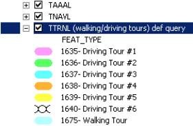
Figure 10.4 Creating a definition query that defines which features belong
in the subset
|
|
|
|
|
The features contained in this
layer will be drawn before the two road layers (TAAAL, TNAVL) as these line
shades need to print beneath the road features. As you can also see, features
within a layer are also drawn to our pre-defined order, from bottom to top.
|
|
By opening up the layer
properties dialog box, a definition query can be stored using a SQL statement
to create a layer that is a subset of the source data. In this example,
Driving Tours will be selected for this layer as defined by the FEAT_TYPES
contained in the definition query.
|
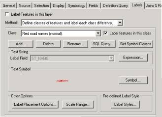
Figure 10.5 How label properties can be defined and stored in a group layer
|
|
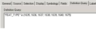
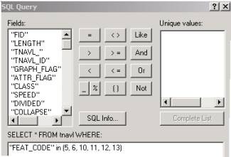
Figure 10.6 Creating a query that defines the label
properties for a subset of features
|
|
|
|
|
Another property the group
layer can store is the label definitions. In this example, primary (red) road
features are set to create red text labels. The same method can be used for
secondary (black) road features, as they will be set to create black text labels.
|
|
In this example, an SQL
query is created to generate red text for red road features. By applying this to the group layer, the
appropriate label color, style and placement options are defined without
input from the user.
|
Conclusion
This paper described how
AAA�s TourBook � maps have been successfully produced using ArcGIS
technology. More specifically it addressed how group layers files are utilized
to automatically render the map features with their corresponding symbology.
The paper also described how to create and utilize a style file to serve as a
repository for annotation and symbol styles.
The test involving the migration
of TourBook � maps into the ArcGIS platform has proven very
successful. Although AAA invested a
great deal of time in setting up the group layers and style files, the effort
is paying off as we have gained great efficiencies in map production. TourBook � production continues to move forward with ArcGIS 8.2
as almost half of the existing 600 TourBook � maps will be
migrated into the ArcGIS environment this year.
There are still, however,
many obstacles to overcome. For example, there are some processes that still rely on the Unix
ArcInfo 7.x system (i.e., pre-selection of features). Furthermore, some of
ArcMap�s native functionality is highly interactive. There are efforts
currently underway at AAA to further enhance the TourBook � production system.
The first of these efforts is to automate
interactive procedures through ArcObjects and Visual Basic. The second effort
is to migrate to an enterprise geodatabase data model. This will allow for the deployment of a
customized suite of tools that will ensure the TourBook � production process is
handled inside the ArcGIS environment, from the initial data extraction to the final
output.
Through
the knowledge gained by the development of an ArcGIS-based TourBook � production
system, the enormous potential of the software has been realized. AAA hopes to continue to work closely with Esri to help
improve ArcGIS� cartographic application. The long-term goal is to eventually
migrate the production of all AAA map products to the ArcGIS platform.
References
For more information on how AAA approaches generalization, refer to the
white paper that was presented during the 2001 Esri conference by Miguel
Garriga titled "Generalization of
Multiple Scale Maps from a Single Master Database".
For information concerning
the conversion of ArcInfo 7.x symbolsets into ArcGIS using the ArcInfo 7.x
Symbol converter, here is the link to the ArcObjects Online page:
http://arconline.Esri.com/arcobjectsonline/samples/arcmap/symbology/symbols/ai
7x symbol conversion/symbolconverter.htm
Acknowledgements
The authors would like to
thank AAA associates Paulo Duarte and Miguel Garriga for the fundamental
support they provided in helping us with this paper.
Authors� Information
Geoffrey Baldwin
Cartographer IV
AAA GIS/Cartography Department
1000 AAA Drive, Heathrow, FL 32746
gbaldwin@national.aaa.com
Mark Dodich
Cartographer IV
AAA GIS/Cartography Department
1000 AAA Drive, Heathrow, FL 32746
mdodich@national.aaa.com