Figure 1: USAR Property Distribution
Abstract:
This paper demonstrates how the collaboration of web technology and GIS software has facilitated improved information dissemination relative to property management. Any organization with a geographically dispersed work force and properties must find efficient, cost-effective methods to share information. Learn how the US Army Reserve Command is using Web-based GIS to organize and distribute organizational and facilities information to promote improved decision making and resource allocation. Facilities planning and management professionals are demonstrating how to leverage geospatial data in the development of an enterprise information distribution platform.
Overview - Concept and Process
Facilities Planning and Management Information
GIS Component
System Security Summary
Site Structure Summary
Future Capabilities
OVERVIEW - Concept and Process
This paper reviews how the collaboration of web technology and GIS software has facilitated improved information dissemination relative to property management. The US Army Reserve Planning Support System is a Web site designed to facilitate the collection and dissemination of facilities planning and management information throughout the Command.
The US Army Reserve Command (USARC) is a geographically dispersed organization with facilities planning and management responsibilities worldwide. Regional Support Commands (RSCs) execute the policies established by Headquarters USARC, but there are limited capabilities to provide ready access to the necessary information needed by staff and leaders to ensure timely and accurate decisions.
A guiding principle in the design and functionality of the site was to provide a tool that consolidates existing information contained in a variety of locations and formats. A "traditional" website design is used to provide a user-friendly interface to this information. In addition, a separate, but integrated Web GIS application was developed to facilitate the distribution of the information from a mapping perspective. Typically, the target users are familiar with traditional map and plan documents so the use of Web GIS technology is an obvious tool to employ for management and distribution of this information involved. ArcIMS™ was selected as the Web GIS tool to distribute this information from a mapping perspective.
Figure 1: USAR Property Distribution
FACILITIES PLANNING AND MANAGEMENT INFORMATION
The Planning Support System provides a secure internet-accessible portal to
the information and data sources that are critical to facilities planning and
management. Primarily, this information includes:
A "traditional" Web site design is used to provide a user-friendly interface to this information. Additionally, a separate, but linked Web GIS application was developed to facilitate the distribution of the information from a mapping perspective. From an information distribution perspective, all data is organized and disseminated based on its association to either the region, a site within a region, or a building on a site.
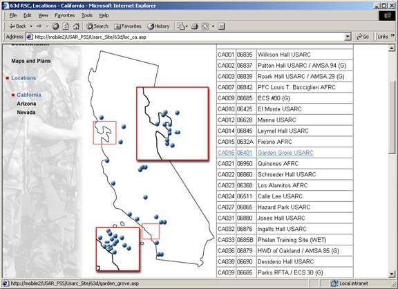
Figure 2: Navigate to a USAR Location
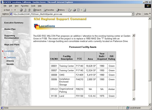
Figure 3: Existing Assets via Site Page
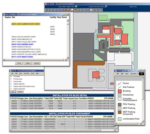
Figure 4: Existing Assets via GIS
The Planning Support System Web site distributes the "official" and typically static information and data output from various sources -- in the format users are accustomed to. That is, traditional "reports" are distributed using PDF format documents, tabular data is provided using Microsoft® Excel spreadsheets, etc. As appropriate, the GIS provides a display of the same information from a supporting database (Microsoft® SQL Server) that is linked to the appropriate map service or feature.
In the above example, after navigating to the Garden Grove property via the traditional web site, the user can view the existing assets inventory via the table on the site page, or via an Excel spreadsheet file. The user can also launch the GIS from this page, arrive at the GIS map for Garden Grove, select the map ID tool and then choose to view the existing assets inventory contained in the IFS data tables in the supporting GIS attributes database.
Overview
GIS Graphic Display - Modular Design Controls
GIS Attribution Display - Modular Design Controls
GIS Navigation Tree
The GIS component of the Planning Support System comprises both a desktop tool utilizing ArcView® 3.2 and the web tool utilizing ArcIMS™ 3.1. As you can expect, the desktop component serves the primary purposes of baseline GIS content development and detailed GIS data analysis tasks. The ArcIMS™ component provides the means to distribute specifically formatted GIS information to the masses using standard Internet and Web technology. A description of the design and implementation of the ArcIMS™ component follows.
Simplified, the GIS data is served to the end-user via ArcIMS™ MapServices that distribute shapefile data developed using ArcView®. This action is made capable using custom-coded HTML and ASP accessed by way of the Web Server sending instructions to and receiving content in return from the middleware. The middle ware comprises a custom-built DLL containing the "business rules and operating instructions" which communicate with the GIS and database servers.
The GIS is designed with flexibility in mind to support a variety of spatial and associated attribute data at any of three defined levels:
Figure 5: Various Display Levels
Based on the modular design of the overall Web GIS application, all of the GIS component content can be easily managed (edited, expanded, or deleted) through the implementation of the application "metadata" procedures implemented in the supporting website database. The use of unique LayerSets, Object Types, Data Sources, and Record Sources controls the availability of both the graphic (spatial) and text (attribution) content.
Employing the use of application metadata to manage the content display has greatly simplified the management of the Web GIS for the system administrator and facilitates the ease by which additional content can be integrated to expand the functionality (and potentially the user base) of the Planning Support System site.
GIS Graphic Display - Modular Design Controls
The GIS component graphic displays are ArcIMS™ MapServices utilizing ArcView® 3.2 shapefiles. At each level, a default map display is defined and opened for the user. However, the actual graphic displays can be readily changed by the user utilizing the LayerSet Manager.
The LayerSet Manager is a custom control developed to support the need for non-GIS users to easily turn on and off data layers in a given map. External data attributes are associated with the active data layers and therefore, the ability to view and ultimately query the attribute data is directly associated with the defined GIS data layers.
Figure 6: LayerSet Manager Control
As shown in figure 6, the LayerSet Manager control opens in a new browser window and the user is able to toggle on or off what LayerSet they wish to have visible. Each LayerSet has a pre-defined "active layer" that is used to support the map and map features identification functionality.
Layers, LayerSets and LayerSetLayers
Figures 7 and 8 demonstrate the differences between the GIS display for the Site Map and the Future Development Plan views for the same location. The system administrator simply manages the available views by managing the MapServices and the corresponding LayerSets.
Figure 7: Site Map View - Existing Buildings
Figure 8: Future Development Plan View - Proposed Buildings
GIS Attribution Display - Modular Design Controls
As all of us that are on the GIS bandwagon already know, the value of a GIS is increased exponentially to the amount of attribution associated with the spatial features. For facilities planning and management, the amount of data associated to our facilities is almost endless. As such, there is extreme value to the users in associating that attribute data to the map features and then distributing it via the Web.
The GIS Component of the Planning Support System implemented the same type of modular design for data identification and management as done for the mapservice layer management (graphic display). Because each LayerSet has a predefined "active layer" it is easy to associated predefined data requests to the appropriate LayerSet. With a simple "show-me-once" training session, the end user can now easily determine which LayerSet is applicable to the attribute data they want to view and then proceed to have the GIS display the desired data. For example:
Figure 9 shows how the user can obtain summary-level facilities information for a specific site based on a Feature ID selection against the dot on the regional map (the feature) that indicates where that property is located.

Figure 9: Regional Map Feature Data
Figure 10 shows how the user can obtain detailed facilities information for an active site map using the Map ID selection on an open site map view.
Figure 10: Site Map Data - IFS Detail
The available data displays are limited only by the definition and development
of stored procedures (data queries) that can be associated to defined object
types within the system. For the Planning Support System, all features (object
types) have a unique data key identifier that is used to associate attribute
data to the specific objects. For example, buildings are uniquely identified
by facility mangers based on their location (a site code) and a facility number.
The combination of these two data elements form a unique identifier for the
building features that can be associated with (joined to) an external attribute
dataset.
Simplified, the following steps outline how easy it is to add new data identification
sources to a mapservice.
Navigation to any location in the GIS is aided by the use of a custom control that implements a "tree-view" navigation form. As delivered, the "navigation tree" for the USAR Planning Support System contains an entry for each property included in the USAR Region (over 1150 properties). Users can "search for and locate" any property on the regional map using the FIND button. As additional GIS data is developed and populated into the system (e.g. site maps, plans, building floor plans, etc.), the property entries in the navigation tree turn blue and the user is able OPEN that map service as well.
Figure 11: GIS Navigation Tree
Figure 12 demonstrates how an authorized user is able to open a specific building floor plan drawing from the regional USARC site by navigating to the desired building in the navigation tree.
Figure 12: Locate and Open a Building Floor Plan from the USAR Regional View
Additionally, users can use the custom "HotLink tool" from any mapservice that has subordinate mapservices. For example, you can hotlink from the installation dot to the installation site map if it is available. Similarly, you can hotlink from building foot prints on a site map to the building floor plan if it exists.
The Planning Support System is a secure site that requires users to log-in and be validated before gaining access. Individuals are granted specific permissions to view all or selected parts of the site based upon the permissions contained in the system security database tables. For example, a USARC level user may logically have access to the data for all locations while a 63d RSC user may only have permission to properties within the 63d RSC area of responsibility.
Figure 13: User Authentication
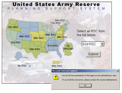
Figure 14: Site Access Warning
The website administrator can quickly and easily manage user access by defining a new user and assigning that user to an existing user-group. If a new user-group is required, the site administrator simply creates the new group, assigns what "regions" that group has access to, and then assigns the appropriate users to the new group. The users inherit the permissions from the user-group.
The Planning Support System is really a series of websites accessible from a single portal. Each Regional Support Command has its own website that conforms to standards established by the site owner (USAREng South). Each site is identical in structure and format to facilitate ease of navigation and "data mining" regardless of which site a user is accessing. Each RSC has the flexibility to "customize" the information content available at each specific location under their control.
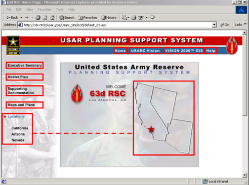
Figure 15: Standard RSC-level PSS Homepage
Figure 16: Standard Property Specific Homepage
Simplified, the Planning Support System comprises five main components as indicated and illustrated below.
Access to the Planning Support System by end users is via their workstation and internet client (Internet Explorer). The Web Server distributes all information requested by the user. A custom middleware component provides the business logic instructions required by the web server to validate users and accurately distribute the information contained within the GIS server and the database servers.
Figure 17: Site Component Architecture
The existing USAR Planning Support System has been developed and deployed as a fully functional prototype to prove the concept of improved facilities planning and management information dissemination. It has been tested and validated by population of selected information / data sets for two RSCs. It has the immediate capability to support all USAR entities as quickly as the content can be developed.
As anticipated, now that the prototype has been deployed and validated as a preferred method of information collection and dissemination, both the functional and information requirements are being reviewed and evaluated to accommodate user-driven improvements. The primary improvements under consideration include the following:
Acknowledgements:
All the participating staff at:
US Army Reserve Engineer Directorate (South)
Colorado DataScapes, LLC
Nakata Planning Group, LLC
Author Contact Information:
Edward C. McConnell, AICP, Vice President
Nakata Planning Group, LLC
719.630.0405, ext 213
emcconnell@nakata.com