Getting Adjusted. How to Get the Most from Your LINK Based Adjustment.
Bart Guetti
Abstract
As higher accuracy data becomes more readily available, the accuracy shortcomings of an organization�s existing data holdings sometimes become all too obvious. What was once thought to be "the locational truth" becomes science fiction. By combining new, higher positional accuracy data with existing data, limitations become exposed, placing the validity of the existing data in serious jeopardy.
Many times the existing data has a large amount of capital invested in attribution, which the organization would like to retain without investing an equal amount in upgrading its locational accuracy. This paper will describe GDT�s Control Vectors product and its implementation of ArcGIS�s ADJUST process for cartographic realignment of transportation related data at a minimal cost.
Introduction
The process of realigning geographic data using GDT's Control Vectors and rubber sheet transformations such as the ADJUST command is a multi step procedure involving vector creation, link import and coverage transformation. Several options exist for the import, transformation and post adjustment processing. Obtaining a handle on these parameters is crucial to a successful feature adjustment endeavor.
Conflation
Conflation is the correlation of two different spatial data sets based upon their geometric and attribute similarities with the purposes of transferring attributes between the two. Geometry conflation compares such characteristics as
Attribute conflation is the correlation of data fields using similarities in
GDT uses conflation for relating its internal vector database to other external databases for the purposes of obtaining higher quality geometry and attribution from the external data source. The greater the similarities in scale, precision and topology between these two databases, the more successful the correlation. However many times there are major differences between the two sets requiring implementation of a sophisticated set of rules to accurately match the features in one set with those in the other. Differences include the location and number of nodes; the location and shape of arcs; and the topological ordering of those nodes and arcs. See Witmer, 2001 for more information on conflation in general and specifically at GDT.
Vectors
There are two main types of correlation vectors produced as a result of the conflation process.
Control vectors are a by-product of the conflation process and are a series of vectors containing the coordinates of the features matched during the conflation process. These are retained and used both internally and sold commercially in a variety of formats. ArcInfo's GENERATE format is one of the formats produced and has a simple from x, y and to x, y format:
-73.997065 41.519468
-73.997168 41.519376
-73.996915 41.519957
-73.997032 41.519861
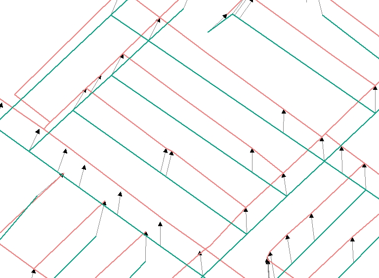
The control vectors in this figure were generated from an area with a rectangular street pattern and a minor amount of geometric difference between the two data sets used. In this figure the vector source layers is green and the destination layer is red.
Constraint vectors represent constraints to movement. These are a series of straight lines, which follow the edges of matched arcs between pairs of control vectors. Movement near these vectors is determined strictly by the control vectors and no movement should occur across this line. An example of a constraint vector in GENERATE format follows:
-74.002512 41.520004
-74.002342 41.520308
-74.002370 41.520451
-74.001274 41.522462
-74.002342 41.520308
-74.002370 41.520451
-74.002118 41.517853
-74.002512 41.520004
Adjusting
The movement of spatial features to a new location using an algorithmic approach (adjusting) is accomplished using a combination of
Using these inputs and tools a rubber-sheet transformation is created and applied to the source coverage to move the coverage's features to the desired location.
Adjusting can be accomplished using each of the following ArcGIS modules
Each module has slightly different options (see Algorithms below) for performing adjustments. For most adjusting the control vectors must first be converted into a link coverage, using Arc GENERATE and then imported into the coverage to be adjusted. Within ArcToolbox adjusting can be done directly from the GEN file without conversion to a link coverage first. Generally the greatest control over the process exists in the ArcEdit environment within Workstation ArcInfo, although more of it is being migrated to ArcMap with each new release. Two types of links can be created and which are used depends upon the situation. Adjustment links are used to indicate the location and extent of movement. Identity links are used to indicate areas where movement should be restricted. Both types of links are generated from the control and constraint vectors and both can be manually added during the editing session.
Environment
There are several environment settings that affect the quality of the adjustment process
These are mostly spatial parameters dealing with editing tolerances. NODESNAP determines the snapping order and distances for nodes. This controls the behavior of the nodes as they are moved to a new location. If it is too large nodes that should not snap to one another, do, resulting in new unwanted intersections or collapsing arcs. WEEDTOLERANCE controls the minimum distance between links. If two links are closer than the WEEDTOLERANCE distance the two will become a single averaged link. This can be a simple way to eliminate redundant links. GRAIN is used to control the minimum distance between the identity links. This is used when specifying the LIMITADJUST area, which is a bounding polygon of the area to be adjusted.
Algorithms
The density, focus and distribution of the adjustment are determined by the sampling interval and transformation method used. The sampling interval options are
The transformation methods are
The sampling and transformation options available depend upon which ArcGIS module is used. The optimal sampling and transformation option for a particular situation depends upon several factors
Process
The process of adjusting coverage features generally consists of
Converting the vectors to links is accomplished with the Arc GENERATE command or ArcToolbox Generate wizard.
To use the vectors within ArcEdit or ArcMap, they need to be imported into the coverage using the GET command. The behavior of the links during import is controlled by the WEEDTOLERANCE command. This specifies the minimum distance between links. If two links are less than the minimum, the two are averaged into one. For most applications GDT uses a setting of a micro degree or .000001 degrees.
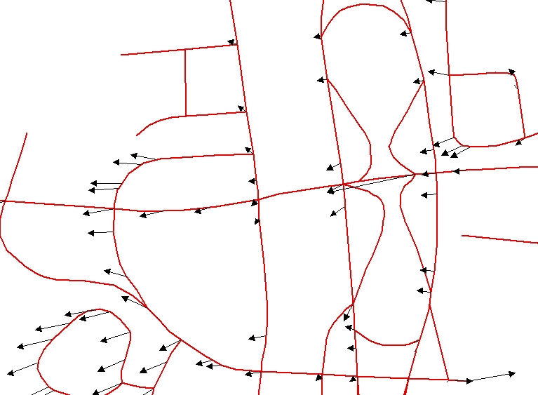
The following figure shows the results of using GET to import the control vector based links into a street coverage.
To reduce the chances of topology corruption, the NODESNAP distance is set to CLOSEST and a snap distance of .000001. Also through the LIMITADJUST step the area to be adjusted, and conversely, the area to be stabilized, is specified. This step allows the user to delete unwanted links and designate the location of identity links, which prevent the movement of features in that area. The GRAIN command controls the minimum distance between these identity links.
The following block of AML code is used to set up the environment and execute the adjustment.
/* WARP.AML 01-17-01
/* Warping demo AML
/* Simple application of the use of
/* GDT Control Vectors GEN file format
/* and Arc ADJUST.
/*
&args inCover outCover sourceCover controlLinkCover constraintLinkCover
ae
disp 9999 3
ec %inCover%
de arcs link
bc %sourceCover% 3
be arcs
draw
nodesnap closest .000001
weedtol .000001
grain .000001
ef link
get %controlLinkCover%
/*get %constraintLinkCover%
limitadjust poly
adjust bivariate
de link off
draw
ef links
sel all
delete
de link
get %controlLinkCover%
save %outCover%
quit no
The following figure displays the results of the adjustment process. The pre-adjusted streets are shown in red and the post-adjusted streets are in purple.
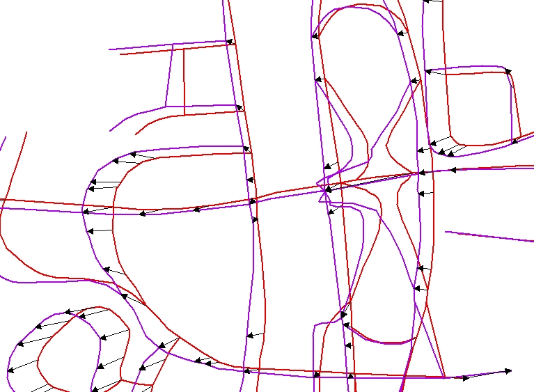
For testing purposes the adjusted street vectors are compared to digital orthophotgraphy.
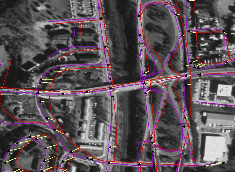
As can be seen from this figure, the adjusted streets now, for the most part, fall within the street casings. There is one area of major confusion caused by the double digitized highway however. Due to the similarity of attribution of the street names at two intersections, an incorrect match was made resulting in distorted geometry when the adjustment process was run.
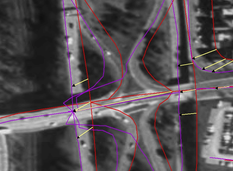
These types of problems can be avoided by refining the match parameters of the conflation process used to create the control vectors to include a one way analysis. This problem could also be avoided by conducting a pre-adjustment edit of the vectors and manual deletion of ones associated with intersection confusion.
Tricks
The quality of the adjustment is a direct result of the similarity of the coverage to be adjusted to the coverage used as the source coverage for vector creation. There are some tricks that can assist in increasing this similarity and improve the adjustment results.
Densification involves adding vertices to a feature where none exist. This improves the reshaping of features during adjustment to more accurately reflect the shape of the feature used in conflation. Shape modifications enabled by this process are especially useful in situations where the features being adjusted correspond to the features used to build the control vectors. An example of this would be where a political boundary coincides with a street. Densification can be accomplished by using the DENSIFY command or by creating vertices via intersections.
DENSIFY allows one to specify a minimum distance between vertices and then apply that to a selected set of arcs. The advantage to this approach is that it is easy to complete. The disadvantage is that the extra vertices make a feature more subject to surrounding vectors that may be associated with other features and have nothing to do with the feature in question which results in an incorrect adjustment. A better solution is densification of features exclusively within the immediate proximity of the control vector. This results in an adjustment that more accurately corresponds to the realignment that has occurred in the area.
Anchors are identity links generated from the features in the data set to be realigned. If a data set possesses a range of data quality, and there are some categories of features that are of a higher quality and you want them to remain in place, then generation of a set of identity links for those features will prevent their movement during the adjustment process. At GDT we do this by first densifying the feature and then creating a set of control vectors from the densified features coordinates.
Post-process
Refinement of the results of the adjustment can be accomplished by
Using the SNAPENVIRONMENT within ArcGIS features in one coverage can be "snapped" to the features in another coverage. By choosing to snap to a more accurate coverage, the adjustment process can provide even better results. By using the control vectors to move the lower accuracy data closer to the more accurate data, the snapping process becomes less prone to confusing features.
If exact coincidence between two data sets is required, as in the case of political boundaries that are defined by physical features, then actual replacement of the political boundaries with the corresponding physical features becomes an option. By moving the two data sets closer together, adjusting assists in the identification of the physical features needed for the replacement.
Finally manual editing to correct errors introduced by the adjustment can be used to complete the realignment process.
Conclusions
Improvements to the spatial accuracy of commercially available data are a constant activity and maintaining an enterprise's relationship with these more accurate data sets is correspondingly a constant challenge. Fortunately GDT retains an important part of its accuracy improvement process and offers it as a solution to others involved with the task of maintaining the accuracy of their data. When combined with ArcGIS's rich set of link manipulation tools, GDT's Control Vectors product offers users an affordable way to ease the burden of this task. When applied correctly these components combine to provide a cost-effective alternative to manual accuracy maintenance. Hopefully this paper has provided some useful insight into how this application can be made more successful.
References
Witmer, Alan W., 2001, The Best of Both Worlds:Vector Conflation of Database Segments and Attributes
for Land Base Migration, 21st Annual Esri User's Conference, San Diego, CA.
Author Information
Bart Guetti
Software Engineer
Geographic Data Technology
11 Lafayette Street
Lebanon, NH 03784
(603) 643-0330
(603) 653-0249 (fax)