Burlington Northern Santa Fe Railroad (BNSF) operates 1,300 trains per day across a rail network encompassing 34,000 miles over 28 states and two Canadian provinces. In order to respond to emergency situations quickly and effectively trains, facilities, and people must be located, identified, and notified in near real time. GIS is well suited to providing the information that decision-makers and emergency planners need. However, facilities and equipment spread across two-thirds of the United States present some unique technical challenges. BNSF's Network Operation Center (NOC) requires applications that allow rapid retrieval and display of massive amounts of geographic data, an easy-to-use multi-user interface for scenario management, integration of BNSF's linearly referenced data into the GIS, and a fault-tolerant client server available 24 hours a day, seven days a week.
SDE on an Oracle database server was implemented for rapid database access, and ArcView GIS extensions on Windows NT clients were developed to produce maps and reports to support emergency response management. Incident management maps can be projected on nine 18x24 foot-wide screen display at BNSF's NOC to assist BNSF personnel in coordinating incident response. The development of the SDE database provides the foundation for integrating GIS applications for other BNSF business processes.
Radian International developed an Emergency Response GIS for Burlington Northern Santa Fe Railroad (BNSF). This system is used for managing derailments that result in chemical spills or other situations that has the potential to impact the health and safety of the populations and the environment along the BNSF right-of-way. In addition, the GIS has been used to manage other incidents, such as vandalism, grade-crossing accidents, and fires, reported by private citizens on or near the BNSF tracks.
The Emergency Response GIS is part of BNSF’s Network Operations Center (NOC), which manages and dispatches trains across 3400 miles of track. The GIS provides rapid access to information on BNSF’s rail infrastructure, chemical spill handling procedures, environmental risks, and demographic factors. This system has been operational since December 1998. The database contains railway, environmental and demographic data for approximately two-thirds of the continental United States. In addition to the massive storage requirements for both raster and vector data, the GIS is a fault-tolerant system available on a twenty-four hour, seven day a week basis. Esri’s Spatial Database Engine (SDE) on Oracle is used to store the vector data. Lizard Tech’s Multi-resolution Seamless Image Database (MrSID) was used to compress and store aerial photography and US Geological Survey Digital Raster Graphics (DRG).
The ArcView client GIS application gives BNSF incident managers the ability to rapidly locate an incident using multiple types of location references (street addresses or BNSF linear referencing system) and generate maps and reports of data pertinent to incident management. This information is used to formulate appropriate responses, notify emergency response agencies and affected populations, coordinate efforts, and document the incident. The ArcView client also acts a data pre-processor to modeling packages such as Complex Hazardous Air Release Model (CHARM), ChemTox, and the American Association of Railroad’s (AAR) Qualitative Risk Assessment model (QRA).
This paper is organized in two parts. The first part of the paper discusses the technical approach to developing the Emergency Response database. This section includes a description of the methodology used to georeference the railroad infrastructure data in BNSF’s Railroad Information System (RIS), the collection and processing of the environmental, demographic, and raster data, and the deployed server architecture. The second part of the paper discusses the ArcView client functionality and its application to incident scenarios.
The primary design criteria of the Emergency Response database included:
These requirements drove the overall design of the system and the database development effort. This section describes the database architecture, the methodology for implementing BNSF’s linear referencing system in GIS, and the spatial data sets that comprise the majority of the Emergency Response GIS.
The GIS database was developed on a Sun Sparc Enterprise 2 on an Oracle 7.3.1 database. Esri Spatial Database Engine (SDE) 3.02 is used for storage and retrieval of approximately 30 gigabytes of data. The production system deployed at the BNSF Network Operation Center (NOC) has the same software configuration, but it is installed on an IBM AIX Unix server.
Because of the size of the layers in the database, the transfer of data from the development system to the production systems was done in phases. Despite the differences in hardware platforms, the transfer of data as Oracle export files is relatively straightforward and does not require additional processing. Fault-tolerance at the BNSF NOC is implemented by a pair of database servers that mirror the GIS database. If the primary server goes off-line, the secondary server is configured to resume serving the data.
The data processing system initially was based on Arc/Info version 7.2 on Sun Sparcs and Windows NT machines. The Arc/Info coverages were loaded into SDE using the cov2sde command. This workflow was abandoned for number of reasons, which included the residual extraneous data (e.g., F_NODE) that is inherent in coverages and inconsistencies between Unix and Windows NT workspaces. The current approach is to use ArcView (Unix and Windows NT) as the data processing, data maintenance, and SDE data loading tool. The exclusive use of ArcView for data manipulation has simplified the workflow and the development of task specific GUIs has improved production speed and accuracy.
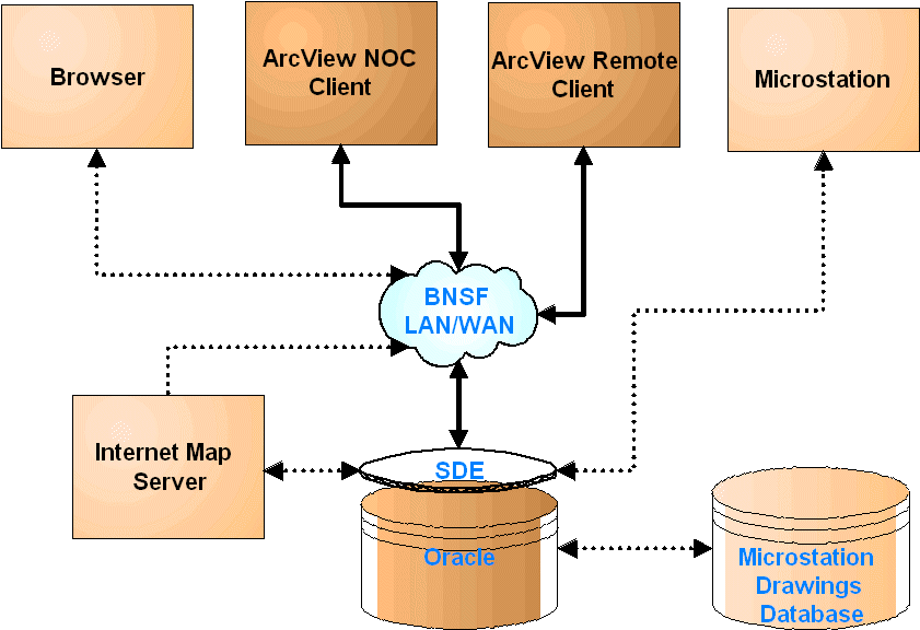
Figure 1. Production system architecture
Figure 1 shows the design of the system architecture. The current system consists of the Oracle/SDE server and ArcView clients that access the data through BNSF’s local and wide area network. Although the system was primarily designed to support incident management, the GIS database can be used for many other BNSF operations. An ArcView Internet Map Server (IMS) can be added to the system, to provide access to the data via a web browser. BNSF maintains their Right-of-Way (ROW) and engineering drawings (straight line diagrams) in Microstation. This data can also be integrated into the GIS database so that drawings of BNSF facilities can be accessed by incident locations. The map server and the CAD file integration are not presently deployed, but are included to show the extensibility of the architecture.
The use of linear referencing systems (LRS) as a means locating facility data is a common practice for organizations managing linear networks such as railroads and roads. BNSF uses a base-offset method of linear referencing, where a section of track is assigned a Line Segment number and the distances along the track are measured from the beginning of the line segment or distance from origin (DFO). Facility data about the tracks (mainline, sidings, spurs), signals, yards, bridges, at-grade road crossings are maintained in a DB2 database called the Railroad Information System or RIS. The primary challenge was to attach geographic coordinates to the data.
In order to tie the BNSF LRS to a geodetic coordinate system, a set of RIS objects that could be related to real word locations were needed. Evaluation of the RIS data showed that the only points of reference were the location of yards and at-grade road crossings. The at-grade road crossings were the only features with sufficient numbers to provide the needed density of points for a reasonable registration between the RIS LRS and the GIS. BNSF did not have a contiguous large scale graphic representation of the mainline track, the track layer was constructed from multiple sources that include the Bureau of Transportation Statistics (BTS) railroads, Census Bureau’s TIGER railroads, and GPS mainline track data from BNSF.
The track data was processed by removing extraneous nodes on each arc and building the network topology so that nodes only existed on the intersection of track arcs. A TIGER based street network was intersected with the cleaned mainline track layer. The resulting layer segmented the mainline track and the nodes provided a point of reference between the road crossings in RIS and the data layers. Once a geographic coordinates could be related to features in the RIS database, it was possible to integrate the BNSF LRS with the GIS mainline track layer. There are several implementation methods for integration. Two methods considered were dynamic segmentation and address geocoding. Route systems and polylineM implementations were evaluated and compared against the address geocoding. For a number of technical reasons, which include the fact that the RIS database was also being redesigned concurrently, the decision was made to use address geocoding as a means to place the facility data along the mainline track. Address ranges were assigned to the mainline track based on the milepost references in the road and bridge RIS tables. Addresses were calculated based on the milepost and line segment fields, then geocoded using ArcView. A shape file for bridges, road crossings, mileposts, signals and yards were generated and loaded into SDE.
Address geocoding ensured that the RIS data was placed relative to the street layer, which permits ArcView to generate maps that are cartographically useful (i.e. the road crossings matched with the roads and the bridges matched with the rivers. Implementation of dynamic segmentation was deferred until the RIS2 database is deployed by BNSF, the RIS2 database is a major redesign of the RIS database and a through data scrub of the distance measures. The recalculated measures in RIS2 will improve the quality of the data used in building the geographic references and improve the locational accuracy of the route systems when dynamic segmentation is implemented.
A study of implementing dynamic segmentation on the existing system has been completed. Implementation of dynamic segmentation is now feasible because of the redesigned RIS data base and BNSF’s current program of using GPS to capture the mainline track. Dynamic segmentation has the advantage of displaying RIS data without creating shape files that need to be maintained. Since the RIS features are displayed dynamically as events on the mainline track, the data will be the most current. The main recommendation is to establish two route systems. The first route system will duplicate the current LRS based on address geocoding; this will allow the ArcView client to continue producing maps that align railroad facilities relative to the street and river networks. The second route system will be based on measures from the link-node network in RIS. The features will be placed in their real world locations, but they may not align with the street network.
This development path is not typical of transportation organizations, because the LRS is usually implemented directly on the GIS layers. However, geocoding was a better solution in light of BNSF’s requirement to produce cartographically sound maps. As the accuracy of the mainline track layer and the RIS data increases, dynamic segmentation can be implemented so that the railroad infrastructure can be displayed relative to the street network and in their real world positions.
The spatial data layers for the Emergency Response GIS are comprised of 24 primary layers that cover approximately two-thirds of the continental US. Table 1 summarizes the data layers in the system. Much of the data was obtained from public sources and processed into a seamless layer and loaded into SDE. Data for sensitive receptors such as schools, nursing homes, and hospitals (populations not easily transported) were purchased from commercial vendors. The street database also provides the data for locating incidents by street name or address. Processing the data for loading did not require additional technical innovation, but the size of the data sets required a well regulated workflow in order to process the data. Regional datasets, particularly threatened and endangered species habitat are also included.
The street data layer was problematic because of its size. This layer holds approximately 8 million records, and it is required for locating incidents with the Locator Tool in the ArcView client. The Locator Tool performs a full table scan on the Oracle table in order to populate pick lists with street names. The response time for populating the pick lists was unacceptable, and as a result the street layer was divided into three layers organized by geography. While this solution was not an elegant design, the Locator Tool menu is populated more rapidly.
In addition to the vector data, the USGS 7.5 minute DRG’s were compressed using LizardTech’s wavelet compression engine into the MrSID. Compression rates of 1:30 were achieved greatly reducing the amount of storage required on the server. The MrSID compressed images are currently stored on a server and accessed through UNC (universal naming convention). Future iterations of the system will load the MrSID images as Binary Large Objects (BLOBs) when ArcView is able to retrieve and interpret the long raw BLOB data from Oracle. Railyard aerial photos were treated similarly and are available through the ArcView client.
|
Data Layer |
Scale/Accuracy |
Source |
|
Schools and Daycare Centers |
1:100,000 |
Abkowitz & Associates |
|
Hospitals |
1:100,000 |
Abkowitz & Associates |
|
Long Term Care Facilities |
1:100,000 |
Abkowitz & Associates |
|
Prisons |
1:100,000 |
Abkowitz & Associates |
|
Emergency Response Teams |
1:100,000 |
Abkowitz & Associates |
|
Law Enforcement Agencies |
1:100,000 |
Public Safety Association |
|
Land use / Land cover |
1:250,000 |
USGS |
|
Soils |
1:250,000 |
STATSGO |
|
Public Water Supplies |
1:250,000 |
EPA |
|
Aquifer Sensitivity |
1:250,000 |
EPA |
|
Wetlands |
1:250,000 |
Fish and Wildlife Service |
|
Population Density |
1:100,000 |
US Census |
|
Streets |
1:100,000 |
Esri |
|
State Boundaries |
1:100,000 |
Esri |
|
County Boundaries |
1:100,000 |
Esri/tiger |
|
BNSF County Boundaries |
1:100,000 |
Esri/tiger |
|
City Outlines |
1:100,000 |
Esri/tiger |
|
Rivers & Lakes |
1:100,000 |
Esri/tiger |
|
Pipelines |
1:100,000 |
PennWell/Map Search Services |
|
Airports |
1:250,000 |
GNIS |
|
Amtrak Stations |
1:250,000 |
Bureau of Transportation Statistics |
|
National Parks |
1:100,000 |
Esri |
|
Other Railroads |
1:100,000 |
Bureau of Transportation Statistics |
|
7.5’ USGS Quads |
1:24,000 |
USGS |
|
Railyard Aerial Photography |
> 1:12,000 |
BNSF |
|
Regional |
Various |
Local, state, federal agencies and private organizations |
Table 1. Data layers in BNSF Emergency Response GIS
The other part of the Emergency Response GIS is the ArcView client application. ArcView's basic functionality was augmented with extensions to access the Oracle/SDE database. The current extensions include the main BNSF extension, the Locator Tool extension, and the Quantitative Risk Analysis data preprocessor. This approach has been successful for deploying applications modularly.
The primary design criterion for the BNSF was to provide a simple to use visual interface to the data. The goals of the ArcView client were:
This section of the paper describes the major functions of the BNSF Emergency Response client software and provides and overview of its application to incident management workflows.
The locator tool (Figure 2) is used to locate areas of interest on the railroad and zoom the display to show a more detailed View of the area. The user can either locate things based upon civilian information (state, city, county, street name) or railroad information (division, subdivision, subdivision & milepost, line segment, line segment & milepost, DOT Crossing Number, Station/Yard Name).
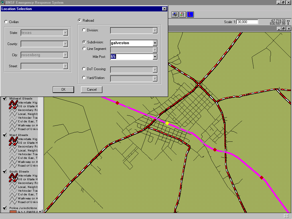
Figure 2: Locator tool
In the civilian mode the user can pick location criteria from selectively more detailed information. In other words, the selection specifications are hierarchical for the civilian mode. This prevents the user from attempting to select a street name from the list of all streets in the U.S. Once a state is selected, then the county and city lists will be populated. When a county or city is selected, the streets for that county or city will be populated and the user can select a street name. The display will be zoomed to the selected area based on the selection criteria. The scale of the zoomed display will be determined by a rectangle that encompasses the selected location. For example if only a state is selected, then the display will be zoomed to encompass the entire state. If a street is selected, then the display will be zoomed to cover the entire length of the street. If there is more than one street with the same name, then the display will cover both of them.
The railroad mode works in a similar manner, except each of the selection criteria are independent of one another and not hierarchical. The only hierarchy is for subdivision and line segments, which have milepost as an additional location qualifier. Keep in mind that milepost numbers may not be unique for a subdivision. Mileposts are unique for line segments.
The locator tool is written as an extension with a custom .dll to provide type-ahead functionality. The .dll uses the SDE API to query the database to populate the picklists in the menu. This approach utilizes the SDE protocols to query the database, which simplifies data handling between ArcView and the .dll. One limitation of this approach is that the .dll does not make use of the existing SDE connection and requires a SDE client license in addition to one used by the main BNSF extension. As a result, two client licenses are needed by the application.
The ArcView client was designed to simplify information gathering for incident management. The graphical user interface provides a rapid and easy means for querying the database and generating reports and maps. The data is grouped into three major themes: environmental themes, demographic themes, and infrastructure themes. These themes are accessed through input menus, and selecting the check box by the menu loads the desired theme. Symbolization and presentation of the data is done primarily through script. In special cases, such as regional data themes, the ArcView legend .avl files are stored in the Oracle databases as BLOBs. This minimizes the need for external files and simplifies software updates. This process is transparent to the user and the appearance of the map display was refined through user input.
Special tools were written for common queries. These tools include:
These queries return information that incident managers need through a simple interface. The system eliminates the need for an experienced GIS user to perform these queries. Figure 3 shows results from the Identify tool.
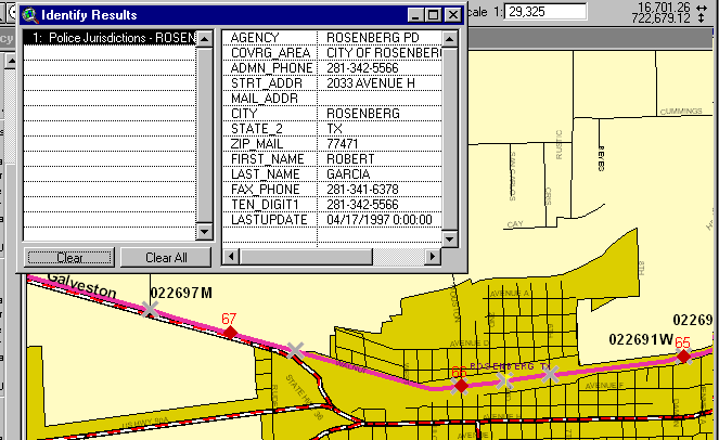
Figure 3. Identify tool results
One of the best features of ArcView is its extensibility. ArcView’s functionality can be augmented through extensions and it can be used to process data for external software. The Emergency Response ArcView client is integrated with CHEMTOX and CHARM. In addition a data-preprocessing tool for the AAR QRA model is available to users.
This CHEMTOX program is used to obtain physical properties, regulatory reporting requirements, spill handling procedures, health risk information, and other information on over 10,000 chemical substances. CHEMTOX is accessed through the interface by clicking on a tool bar button. When the user finishes using CHEMTOX, exiting the program will return the user to the GIS.
CHARM is a sophisticated modeling program for generating a plume map to show where a substance released into the air as a result of a derailment will spread based upon the weather, substance, and spill scenario. A simplified user interface is supplied with the BNSF Emergency Response GIS to access CHARM capabilities quickly. The user can choose the substance released, the release scenario, the wind conditions, and the time since release (see Figures 4 and 5). Predefined scenarios are defined to simplify use of the program. Alternatively, the user can specify the scenario (substance and release conditions) directly. CHARM users are trained in the use of that program. CHARM can also be run in a standalone mode to gain access to the full capabilities of CHARM.
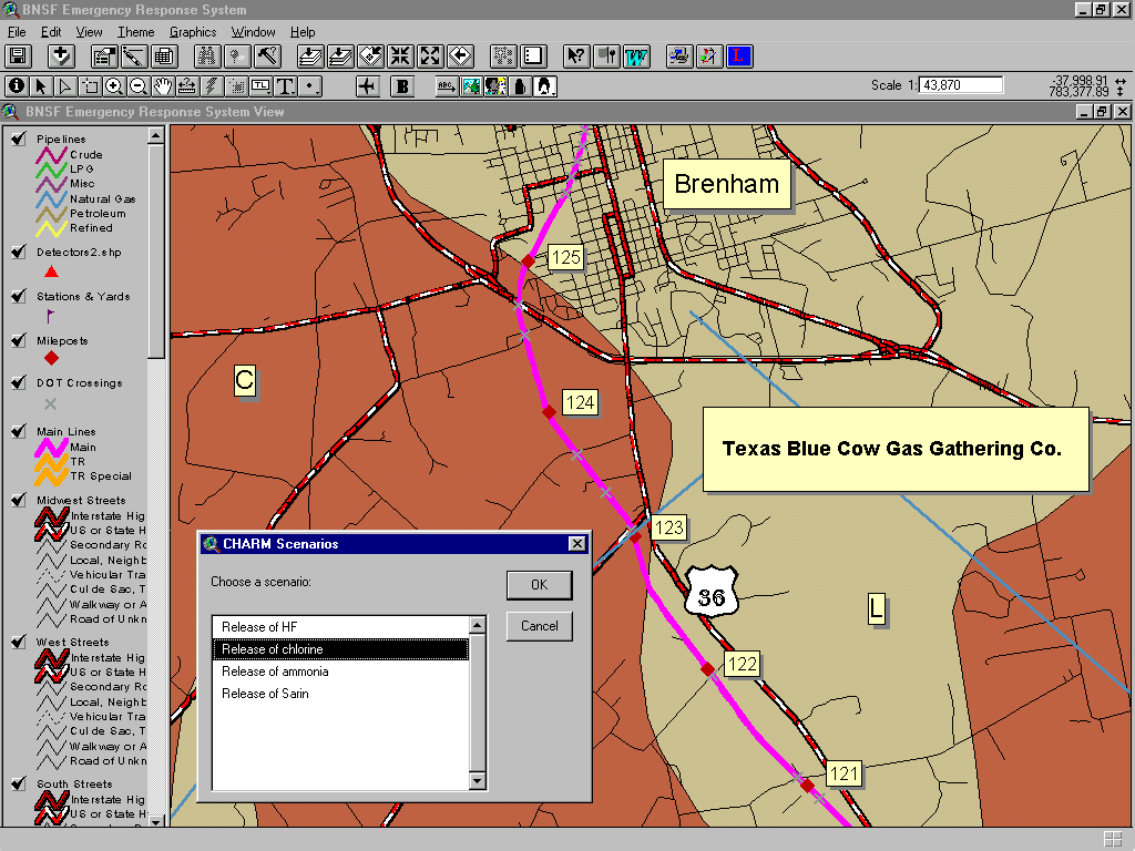
Figure 4. CHARM scenarios

Figure 5. CHARM release plume displayed in Emergency Response GIS
The QRA data preprocessor is used to generate model input data from the GIS. Model input was typically gathered manually by measuring the distances along the railroad on maps. The data was entered into the model as segments defined by changes in the different variables. GIS is well suited for this type of data gathering activity. The model data is written to a file suitable for importing into the QRA program.
This paper describes the first iteration of the BNSF Emergency Response GIS. The current configuration performs well as a tool for incident management. However, as BNSF personnel use the system, application of the data and spatial analysis tools beyond incident management become more apparent. Implementing dynamic segmentation is currently under testing as well as improving the mainline track geometry using GPS. As mentioned previously, address geocoding was used to locate features in order to avoid rubber sheeting and conflation. However, the geocoded railway network can be converted to a route system if dynamic segmentation is implemented. Establishing the route system will eliminate the need to create railroad infrastructure data layers (yards, signals, road crossings, etc). The layers will be created dynamically from a query of the RIS database. The most obvious advantage of this method is that the data will always be recent and maintenance of data layers will be minimized. The second, advantage of dynamic segmentation is that other BNSF business data can be included into the GIS, such as right-of-way data. The ultimate goal of implementing dynamic segmentation is to have the system provide data driven maps and information for a wide variety of applications.
The system architecture based on an Oracle/SDE server and ArcView as the client software has proven to be a flexible and robust architecture. SDE data is transferred between the different platforms routinely. This data is available to users via ArcView, which has been customized to simply reporting and map generation. In addition to tools for incident management, additional functionality has been added through ArcView extensions and integration with other software packages. Deploying these applications in the ArcView client has been relatively easy. Based on past deployments, additional functions and improvements to the client software will be straightforward. Improving the quality of the mainline track data is the next task in the BNSF GIS development process.