Assessing Risk to Public Health from
Petroleum Contamination in Potable Wells
Using the Geographic Information
System (GIS)
Bureau of Water Programs
SUPER Act
January 2003
Larry Gordon


|
Assessing Risk to Public Health from |
|
|
|
|
|
|
Table of Contents
Abstract
Introduction
SUPER Act Program
Well Surveys
Potable Well Sampling
Contamination Tracking System
Case History
Arc IMS
Summary and Conclusions
Author Information
Figures
FIGURE 1 - Potable Well Survey
FIGURE 2 � Database Query
FIGURE 3 � Contamination Map.
FIGURE 4 � Sample Summary Report
FIGURE 5 � Gas Mart Area Map
FIGURE 6 � Benzene Plume Map 2002
FIGURE 7 � Arc IMSABSTRACT
The Well Surveillance Section of the Florida Department of Health (DOH) locates and identifies petroleum-contaminated facilities and surrounding potable wells using sophisticated global positioning system equipment (GPS). Drinking water wells identified in a GPS survey are sampled and the water analyzed by the DOH's Jacksonville Laboratory for volatile organic compounds and other potential groundwater contaminants. Since 1998, the DOH has located over 10,000 petroleum sites and completed GPS surveys to locate, identify and sample over 20,000 private and public drinking water wells. The primary purpose of the Well Surveillance Section is to identify drinking water wells potentially contaminated with petroleum and assist in getting wells remediated if there are potential adverse health impacts due to groundwater contamination. A secondary objective is to assist the DEP in assessing the priority for contaminated site cleanups. The DOH manages a comprehensive Geographic Information System (GIS) database that is used to generate high-resolution well survey maps, conduct spatial analysis for specific contaminants, and provide a tool for remediation and risk-based assessments. The ultimate purpose of our work is to protect the health and welfare of all citizens of the State of Florida by ensuring a safe drinking water supply.INTRODUCTION
This paper describes the Florida Department of Health�s (DOH) strategy to assess, monitor and remediate petroleum contamination in potable water wells using Geographic Information System (GIS) utilities. Environmental Systems Research Institute, Inc. (Esri) ArcGIS� and other database management tools, including Microsoft Excel� and Access�, are regularly used by DOH Well Surveillance staff to evaluate public health risks from contaminated water in potable wells located near documented leaking underground storage tank (UST) sites. Information used to characterize contamination is obtained from the DOH Bureau of Laboratory�s Sample Manager database, Global Positioning System (GPS) databases maintained by the DOH State Underground Petroleum Environmental Response (SUPER) Act Program, the Florida Department of Environmental Protection (FDEP) Oculus and other private and governmental agencies. Typically, DOH Well Surveillance staff located in Tallahassee generate maps and tables for interpretation of the quantity and type of petroleum contamination plumes in ground water near potable wells. These �contamination tracking� maps are used to improve field staff�s understanding of plume geometry and movement. Better understanding of ground water contamination movement allows for more efficient and cost effective sampling and monitoring of potable wells.
Site-specific examples described in this paper provide an overall characterization of plume geometry, direction of ground water flow, attenuation and forecasting of future plume migration. This type of risk assessment tool can be very effective in determining if wells in the path of a moving plume will be adversely impacted by petroleum contamination. Such information can be used as an early warning signal in the affected areas allowing for sufficient time to plan for alternative water resources.
Special thanks and appreciation are extended to Laura Kramer, Environmental Specialist with the Volusia County Health Department, staff of the Martin County Health Department SUPER Act program, Tallahassee Department of Health Well Surveillance staff, and the Florida Department of Environmental Protection�s Bureau of Petroleum Storage Systems (BPSS).
SUPER ACT PROGRAM
In 1986, the Florida Legislature created the State Underground Petroleum Environmental Response (SUPER) Act Program in response to ground water contamination resulting from leaking underground petroleum storage tanks. The primary authority for the SUPER Act Program was given to the Florida Department of Environmental Protection (DEP). DEP oversees the clean-up activities around petroleum storage system facilities that have had a loss of petroleum product. The Department of Health (DOH) SUPER Act Program, pursuant to Chapter 376.3071(4)(g), Florida Statutes, was given authority to provide field and laboratory services, toxicological risk assessments, investigations of drinking water contamination complaints and education of the public.
Recognizing the number of contaminated facilities and the threat to drinking water, the DOH was given public health responsibility to identify drinking water wells around SUPER Act facilities. In addition, a representative number of drinking water wells are sampled for petroleum contamination. DOH Tallahassee coordinates the statewide program and local County Health Departments (CHDs) perform most of the fieldwork including GPS and sampling. Since the program�s inception, DOH has investigated the majority of known contaminated sites statewide and has sampled thousands of drinking water systems. Primary SUPER Act tasks that CHDs are responsible for include conducting well surveys, sampling potable wells and monitoring wells with known contamination problems.
WELL SURVEYS
Today, it is routine for DEP to request that DOH investigate SUPER Act facilities to determine their priority ranking of cleanup in accordance with Chapter 62-771, Florida Administrative Code (DEP�s Petroleum Contamination Site Priority Ranking Rule). By rule, SUPER Act facilities with drinking water wells in the immediate site vicinity are given higher priority for funding in the cleanup program. Procedures have been standardized to ensure the well survey investigations are conducted in accordance with protocols for Global Positioning System (GPS) to locate wells. Also, drinking water sampling is conducted in accordance with DEP Quality Control/Quality Assurance procedures. A SUPER Act Technical Guide has been published to provide CHDs with policies and procedures for conducting potable well surveys (DOH, 2001). A GIS map and well survey data is used for site ranking purposes (Figure 1).
FIGURE 1 - Potable Well Survey � Center underground tank symbol indicates the location of a known petroleum contaminated site and small circles represent locations of potable drinking water wells in the site vicinity. Larger circles represent the � and � mile buffer distances away from the facility being surveyed. In this example, all potable wells located within � mile of the facility being investigated are sampled for volatile organic compounds (VOCs) and the total number of wells counted is used to determine the priority ranking of the site for eligible cleanup funds.
After a well survey request is received from DEP, the CHD investigator identifies the petroleum facility in the field and all potable wells within a 1/4-mile radius of the facility. All public supply wells (>100,000 gallons per day permitted capacity) are identified within a 1/2-mile radius of the facility. Facilities and wells are located with real-time Differentially Corrected Global Positioning System (DGPS). All wells are labeled with a Florida Unique Well Identification (FLUWID) tag and plotted on an ArcGIS� generated map at the headquarters office in Tallahassee.
Construction of potable well survey maps using ArcGIS� involves several steps. Initially, the GPS coordinates for facilities and wells identified in the field are electronically submitted as a data file to a central e-mail address (GLOBAL) where database specialists assure the quality (QA), formatting and content of the file for completeness and accuracy. The DOH uses several types of DGPS units to survey wells and facilities; however the standard equipment consists of receivers capable of less than 2-3 meter accuracy. Separate data files are maintained in data loggers attached to the receivers for storing UST (facility) locations and potable wells. Each GPS data file contains latitude and longitude of the location in WGS 84 (World Geodetic Survey) coordinates and demographic information such as name, owner and address. Other optional fields include information such as well construction details, GPS date, comments, etc. The GPS coordinates are recorded electronically and never manually entered or edited in the database. Also, the data file for each facility and well includes unique identification numbers that eventually will be used to develop cross relationships between various databases including the GPS locational data, sample profiles and sample analysis results.
After data files have undergone a thorough QA review, the data file is imported into the appropriate Microsoft Access� facility or well table and is linked directly to the ArcGIS� mapping system. At the time of this report, the DOH�s underground storage tank facility table contained approximately 10,000 GPS locations and the potable well table contained approximately 20,000 GPS locations. Once the tables are linked to ArcGIS�, facilities can be searched and located on a street map or digital orthophoto quarter quadrangle (DOQQ). On a street map drawn to a scale of 1:12,000, �-mile and � mile buffers are added to show the distance relationships between contaminated facilities and wells. The DEP uses the final potable well survey map to determine eligible �points� based on the number and type of wells located within the identified buffers (Figure 1). For example, a facility with more than ten potable wells located within � mile earns 20 points. If less than 10 wells are found, the facility earns only 10 points. The use of GPS/GIS produces a very accurate and unbiased well survey map.
POTABLE WELL SAMPLING
Following completion of the well survey, up to ten potable wells that were identified in the survey within � mile of the leaking UST are sampled and analyzed for volatile organic compounds (VOCs) that could be present in petroleum contaminated ground water. Drinking water that contains VOCs can increase the risk for a variety of health problems including cancer. Wells that exceed the maximum contaminant level (MCL) or health advisory level (HAL) for a list of identifiable VOCs, such as benzene and methyl-tert-butyl-ether (MTBE), are usually either connected to city water or granular activated carbon (GAC) filters placed on the well to remove the contaminant. Additional monitoring is then conducted to focus on other nearby area wells to evaluate the potential for a spreading �plume� of petroleum-contaminated ground water.
DOH routinely samples potable wells in the vicinity of known petroleum contaminated facilities to ensure that ground water remains safe to drink while assessment and cleanup operations proceed. The frequency of monitoring depends mostly on the amount of VOCs detected in the last sample collected, but can also be determined by the immediate threat and concentration of contamination sources. If concentrations of the respective VOC compound are detected in amounts exceeding � MCL or HAL, the potable well is sampled quarterly until it is determined the source has been removed and the potential for further contamination has been eliminated. If concentrations of the respective VOC compound are detected less than � of the MCL or HAL, the potable well is sampled annually. However, if VOCs are not initially detected in surveyed wells, CHDs are encouraged to sample up to five representative wells close to the contamination source at least once per year. These procedures are followed until the source has been removed by remediation or natural attenuation, and the potential for further contamination eliminated.
To ensure that all potentially impacted wells within � mile of a contaminated site are tested regularly for VOCs and to conduct routine monitoring as efficiently as possible, DOH specialists have developed database search tools within ArcGIS� and Access� to quickly �zoom in� on areas of concern due to known contamination. Essentially, these tools consist of database queries that match detections of contaminants at specific threshold concentrations with their respective coordinates in ArcGIS�. For example, one query is designed to search for all potable wells in the database which have concentrations of benzene detected in the water sample from a well greater than 0.5 ppb (parts per billion), or � of the MCL of 1 ppb for this compound. In this example, the FLUWID number record in the sample table provided by the laboratory is cross referenced with the respective FLUWID number record found in the GPS table for all potable wells to obtain a unique location for the sample result (Figure 2).
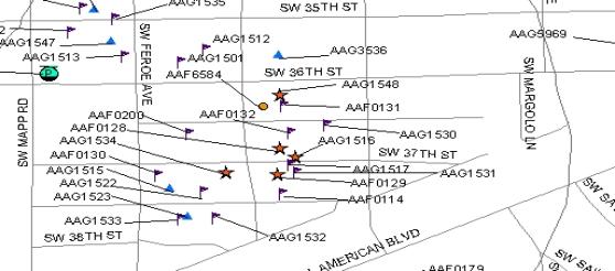
DOH has designed a series of queries that can be used to conduct spatial analysis of petroleum contamination in ground water in the vicinity of potable wells. Query tables are linked to the ArcGIS� mapping system and the data is plotted with various symbols used for depicting the sampling history in the area of concern. Figure 3 shows an example of how these GIS tools can be used to improve the monitoring of potable wells in contaminated areas. In this example, wells that have been significantly impacted by petroleum in the ground water are shown as stars because greater than � of the MCL/HAL has been detected during the most recent water sampling event.
FIGURE 2 � Database Query � Microsoft Access� design query option is used to match locational data (Longitude & Latitude) from the GPS wells database to the laboratory analysis results database. The example above is designed to search for all results having benzene detected at greater than 0.5 ppb. Tables are cross-referenced using unique well FLUWID and Sample identification numbers.
FIGURE 3 � Contamination Map � Tank symbol (circle with P) indicates the location of an underground storage tank site, stars are locations of potable wells with detectable concentrations of VOCs greater than � the MCL/HAL, small circles are wells with detections less than � the MCL/HAL, triangles are potable wells with no detections in the past year and flags are wells that have not been sampled in over one year. Arrows indicate the predominant direction of ground water flow.
Other symbols are used for wells that had either no detectable hydrocarbons or only trace amounts of VOCs detected during the most recent sampling. Also, some wells are represented by flags to alert the investigator that the well has not been sampled in over one year. Wells with detectable levels of dissolved VOCs that are also �clumped� together may indicate a pattern of contamination in the ground water typical of a �plume� that moves in the direction of ground water flow. Additional information about plume geometry and movement away from a petroleum source area can be readily obtained from files at the FDEP�s Bureau of Petroleum Storage Systems (BPSS). Contamination Assessment (CA) reports contained in the Oculus Document Management System archive often show plume geometry and movement in the shallow portion of the aquifer.
Evaluated together, the GIS potable well table, sample results and archived data for individual leaking USTs can be used to reliably interpret the movement of petroleum contamination in the ground water and its potential to impact a potable well. In Figure 3 above, flagged wells located near starred wells should be sampled as soon as possible since evidence suggests that a plume of petroleum-contaminated ground water significantly threatens these wells. Also, as more data becomes available with additional sampling, the plume geometry and movement becomes more apparent and predictions will improve regarding the risk to other wells in the area. CHDs that have become familiar with the facility in Figure 3 are aware that a plume of petroleum contaminated ground water is moving in a southeasterly direction away from the source at the UST site. Consequently, sampling efforts have been concentrated in wells �downgradient� of the known leaking UST.
CONTAMINATION TRACKING SYSTEM
The DOH has developed a contamination tracking system that currently includes over 100 potable well locations throughout Florida that have detectable levels of VOCs above the � MCL/HAL threshold. Future efforts will focus on wells with even trace levels of contaminants identified. Many of these wells have been fitted with granular activated carbon (GAC) filter systems due to the detection of VOCs at levels above the MCL/HAL threshold. These filter systems are monitored quarterly to ensure that the treated water meets safe drinking water standards. All laboratory analyses are conducted at the DOH Jacksonville lab in accordance with EPA method 524.2 (Drinking Water Volatile Organic Chemical (VOC) Package Method). Also, DOH annually monitors a representative number of potable wells within � mile of all known petroleum contaminated sites regardless of a previous history of clean samples. Occasionally, wells are added or dropped from the quarterly contamination tracking system due to plume migration, source removal and/or natural attenuation.
Every three months, DOH maps detectable benzene, toluene, ethyl-benzene, total xylenes (collectively referred to as BTEX) and methyl-tert-butyl-ether (MTBE) contamination in potable wells using ArcGIS� as described on page 5. At that time, a map identification number is assigned to the layout. The map identification number is a unique number based on the year contamination is discovered and the order of which it is mapped in that year. The order of mapping is generally based on the level of contamination with potable wells having the highest detectable levels of VOCs mapped first. Upon completion, each map is sent via email to the appropriate CHD with a summary report including the contamination history of all wells marked within the � mile radius of a known contaminated well (Figure 4). In addition to the map and sample analysis summary report, recommendations are provided for follow-up sampling in the area. Also, in accordance with program requirements established in the SUPER Act Technical Guide, all wells with VOCs above � the MCL/HAL must be sampled quarterly.
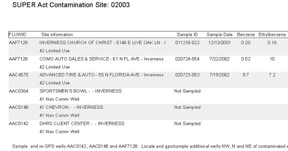
Sample analysis Summary Report (Example is not a complete version of the standard report)
*Benzene and Ethyl-benzene concentrations are in parts per billion.
FIGURE 4 � Sample Summary Report. � In addition to maps, summary reports are generated each quarter for contamination tracking. In this example, well AAC4575 has been fitted with a GAC filter system because the 9.7 ppb (part per billion) concentration of benzene exceeds the safe drinking water MCL of 1 ppb. Note that a nearby well AAF7128 detected a concentration of benzene at 0.52 ppb. Since this level exceeds � of the MCL it is automatically scheduled for quarterly sampling.
CASE HISTORY
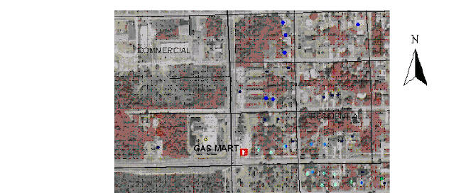
In 1988, a petroleum facility in Florida, hereinafter assigned the fictional name Gas Mart, discharged sufficient amounts of gasoline from leaking USTs to contaminate private drinking water wells adjacent to the site for a distance of up to � mile. Monitoring of these wells by the DOH began in 1988 and continues today. Historically, at different times petroleum contamination has been identified in more than 30 wells at homes to the east and southeast of the facility (Figures 5 & 6). The shallow, potable aquifer in the area is particularly vulnerable to contamination due to the lack of any significant confining layers. Many of the wells in the area have exceeded the MCL for benzene and MTBE and are now connected to city water.
Previous work by the DOH, including extensive GPS surveying and sampling of private wells, documented a typical and highly developed petroleum plume in the ground water that originated from the leaking USTs at the Gas Mart (Figure 6). On May 26, 1988, the Gas Mart facility submitted to the DEP a petroleum contamination discharge notification form requesting eligibility for cleanup funding through the DEP�s Early Detection Incentive (EDI) program.
A contamination assessment (CA) at the facility concluded that benzene and MTBE in the ground water were present in the vicinity of the USTs at concentrations greater than MCLs for these hydrocarbons, both constituents of gasoline. The CA report indicates the facility did not report any significant loss in inventory, or leaks in the tanks. However, contamination was reported in monitoring wells located in the immediate vicinity of the tanks. Soon after the discharge was reported, sampling began in the residential area located to the east of the facility (Figure 5). Due to significant petroleum impacts to many of these wells, the residents were connected to the local public water supply system for drinking water. Clean up of the leak at the Gas Mart was completed and approved by DEP in 1999. The site is no longer on DEP�s list of contaminated facilities. However, about 15 private potable wells east of the site are still affected by the contamination in the ground water. The affected wells are all located approximately �-mile away from the facility in the direction that ground water flows naturally (Figure 6).
FIGURE 5 � Gas Mart Area Map � The above aerial photograph shows an actual leaking UST site located in southern Florida. The UST facility is given a fictional name (GAS MART) and is marked with the pump symbol in the small box near the center of the photograph. Numerous private potable wells are located directly east of the facility adjacent to the small homes seen in the right half of the photograph.
FIGURE 6 � Benzene Plume Map 2002. � Shortly after petroleum contamination was detected at the Gas Mart in 1988, the local CHD began sampling potable wells located within � mile of the facility. The results of the initial sampling indicated benzene in several private wells directly to the east and southeast of the facility. Note that there are relatively fewer wells in the neighborhood located immediately southeast of the petroleum facility. This area has been supplied with community water since about 1990 due to historic contamination in that area. Benzene concentrations detected at levels exceeding � of the MCL in water sampled from the wells in 2002 are shown as stars at the actual GPS locations. The plume of contaminated ground water has moved progressively further to the southeast since 1988 and is typical of a benzene plume migration path in a shallow, relatively porous unconfined aquifer.
Until recently, DOH�s contamination tracking system for the Gas Mart, and similar areas of contamination, has consisted of hand drawn maps showing potable well locations impacted by benzene and MTBE plumes. Also, the local CHD has maintained water sample analysis result tables for different periods of time throughout the 1990s that can be used to evaluate the rate of plume migration and determine the wells downgradient that potentially could be affected. Although natural attenuation processes and biodegradation has reduced the concentrations of contaminants found in the ground water and removal of the leaking USTS has removed the source, the plume has continued to move eastward over � mile with some wells recently testing positive for benzene above 1 ppb for the first time.
Presently, DOH maintains all records of potable well contamination in the vicinity of the Gas Mart in Access� database tables, which include well coordinates, sample history, demographics and laboratory analysis results. Using standard query reports with direct links to ArcGIS�, maps can be quickly updated and submitted to CHDs via email for planning future monitoring activities. These same reports are used by DEP staff involved in the cleanup program to plan for future alternative water supplies including cost-benefit analyses for extending public supply mains. The GIS contamination tracking system also allows users to quickly generate reports summarizing a particular well�s sample history, map other wells within a specified distance of the contaminated well, and show the current status of other wells in the area. Successful tracking of potable wells and predicting plume behavior requires that all wells be surveyed by GPS and downgradient wells be sampled quarterly if possible for VOCs.
ARC IMS
In January 2003, DOH will introduce an Internet map server (IMS) application to the general public that will allow users to create their own custom GIS maps online. Similar to the ArcView 8.0 application currently used by DOH to create well surveys and contamination tracking maps, Esri�s Arc IMS� application can be used to create these maps online using data contained in the SUPER Act facilities and well database. Arc IMS� is a simple and cost-effective way to implement GIS on the Web and reach a vast audience. In addition, the easy-to-use browser interface lets anyone use the Web to access maps with no training or experience in the use of GIS based applications.
Arc IMS� users will be able to view the facilities and wells on a statewide map and use standard GIS tools including search, zoom, pan and identify. Also, the application will be customized to allow users to add additional GIS layers such as county boundaries, streets, water bodies and non-potable wells. Finally, maps can be printed or exported for use in other applications. Figure 7 shows the layout of the program functions and customized layers.
FIGURE 7 � Arc IMS� Application � In January 2003, DOH will launch a web-based application that will allow users to create their own well survey maps. In the example above, the user can search for a petroleum contamination facility in the SUPER Act database and then locate all potable wells within a specified distance from the facility. The dots shown on the web-browser represent potable wells within � mile of the highlighted petroleum contamination facility. Clicking on a dot using the identifier tool will provide specific information regarding the well owner�s name, address and identification number. Also, maps can be printed showing these features in relationship to other layers in the database including streets, highways and water bodies.
SUMMARY AND CONCLUSIONS
The Florida Department of Health (DOH), Bureau of Water Programs locates and identifies contaminated facilities and surrounding drinking water wells using sophisticated global positioning system equipment. Specially trained County Health Department personnel conduct GPS surveys using real-time, differentially corrected GPS to locate facilities and wells within less than 2-3 meter accuracy. Drinking water wells identified in a GPS survey are sampled and the water analyzed by the DOH�s Jacksonville Laboratory for volatile organic compounds and other potential ground water contaminants. Since 1998, the DOH has GPSed nearly 10,000 petroleum contaminated sites and completed GPS surveys to locate, identify and sample nearly 20,000 private and public drinking water wells in their vicinity. Funding for these programs is provided by the Department of Environmental Protection through the State Underground Petroleum Environmental Response Act.
The DOH manages a comprehensive Geographic Information System (GIS) database that can be used to generate high-resolution well survey maps, conduct spatial analysis for specific contaminants, and provide a tool for remediation and risk-based assessments. GIS is a highly effective tool to manage and assess a large volume of data concerning petroleum contamination impacts to local ground water resources. Since thousands of private well water samples are collected each year for VOC analysis, the GIS tool in conjunction with database queries is the only practical method of evaluating a large number of sites and at risk wells within a minimal time period. DOH has found that GIS users can quickly determine if a private well in the vicinity of a contaminated site is in danger of becoming contaminated, or if the risks are minimal. Evaluation of potable well sample results in conjunction with ground water sample results from monitoring wells can improve the overall characterization of plume geometry and movement. Better understanding of plume behavior increases the likelihood that petroleum impacts to drinking water resources will be recognized early on and the appropriate monitoring and remediation measures applied. The ultimate goal of DOH�s efforts is to protect the health and welfare of all citizens of the State of Florida by ensuring a safe drinking water supply.
For more information regarding the SUPER Act Program, visit our website at http://www.superact.org. For information about the Department of Health visit http://www.doh.state.fl.us.
AUTHOR INFORMATION
Author: Larry Gordon
Environmental Manager - SUPER Act Program
Address: Bureau of Water Programs
Florida Department of Health
4042 Bald Cypress Way
Bin C-22
Tallahassee, Fl 32399
Phone: (850) 245-4240
Fax: (850) 922-5549
E-mail: larry_gordon@doh.state.fl.us