Greg Thomas
Neal Millett
Fairfax County Virginia GIS: Planning, Design and Implementation - The Critical Steps
Abstract
Fairfax County is Virginia's most densely developed jurisdiction with over 900,000 residents and over 325,000 parcels within 399 sq. miles. Fairfax has recently completed a large GIS conversion to build a planimetric base and more accurate parcel/zoning data set for use across County operations. Accurately converting Mylar-based Assessor's data into a complex GIS structure is an essential, though challenging, component of the process. System management, data validation, conversion operation, and QA/QC requires project and strategic management. This paper addresses the lessons learned from this program that other agencies will find beneficial for planning and managing a GIS conversion.
Project Background
Fairfax County
Fairfax County, located just outside of Washington, D.C. in northern Virginia, encompasses 399 square miles of area and is home to more than 900,000 people residing on 330,000 parcels of land. Over 250,000 buildings are also in the county, along with 1,000 bridges/overpasses and 3,400 miles of road. This presents a large GIS data modeling and data management challenge.
The County GIS Branch is part of the Department of Information Technology (DIT). The GIS currently has 20 staff working in the areas of application development, customer service, data management, and geodata & systems technology. Being located in DIT enables GIS to be a countywide service, just as communications, and enterprise data processing are.
The County currently uses Esri products for its GIS work. Arc/Info is the professional software that is used in the GIS office for maintaining all of the data layers and performing advanced spatial analysis. Most clients use Arcview to perform queries against the database and produce map products. Map Objects is being used as an integration tool to implement GIS into business processes. Internet Map Server technology is being used to disseminate GIS information throughout the County using the internet/intranet.
The Data Conversion Project
Fairfax County has been maintaining hard copy map products for many decades. The Mylars that are the basis for the hardcopy products were becoming tattered and worn and were going to need replacement. So many layers of data were contained on the Mylars that there was little if any capacity for more data layers to be added. Also, the hard copy source did not promote ease of access to the most current property mapping information.
The County wanted to develop a GIS to maintain the property/zoning maps, to link spatial information to enterprise databases and to do spatial analysis with the property data. There was also a need to develop applications that would change the way people do business in the County.
This paper describes Fairfax County's large-scale data conversion process. The mapping program is discussed with respect to the mapping functions that are performed, the products that the mapping department maintains and provides to the public, and the staff that work in the GIS department. This paper also discusses preparation for the conversion process: the hardware, software, and database requirements and how the source documents were prepared for data capture.
Vendor procurement is covered and includes developing the RFP, reviewing submitted proposals, and negotiating the contract. The vendor's perspective for managing the process of converting this large amount of information is also discussed. The pilot project, status meetings, progress tracking, data capture, accuracy requirements and managing sub-contractors are discussed as well.
Finally, there is an overview of the status of Fairfax County GIS now that the conversion process has been completed. This encompasses the products of the data conversion effort and planned updates. Lessons learned are also included.
Past Mapping Program
Mapping Functions
In order to maintain the property and zoning maps for Fairfax County, the GIS Branch has developed a standard maintenance process. When an update comes into the GIS office (from various sources) it is put onto a paper copy of the Mylar tax sheet called a revision sheet. Once there are sufficient changes to a revision sheet, the GIS Technicians take the information and ink it onto the Mylar. The inking process is very time intensive, and leaves lots of room for error and for non-standard cartographic elements. In other words, the GIS Technicians don't always follow a set standard, particularly over a 20 year period.
The GIS branch prints a hardcopy 1" to 500' scale tax map book once a year that is distributed to over 1000 people/agencies within the county. This is an annual snapshot in time of the property and zoning map sheets. If a more current version of a map sheet needs to be seen, the person must come to the GIS offices, research the revision sheets and then look at the plats to determine the parcel configuration from the revision sheets and Mylars.
The GIS branch is in charge of assigning the property identifier for every parcel in the county. Once a site plan has been submitted and an address has been determined, a unique parcel identifier is assigned. The County's tax assessment office uses the parcel identifier to create an assessment card for the new property.
These functions are very time consuming and laborious in a hard copy world. These reasons lead to the need for a digital version of the property and zoning. The digital data is current, available to nearly anyone with a computer system, and easily maintainable. The parcel changes can also be put into electronic workflow processes and monitored to determine where it is in the process.
Staffing
The GIS branch in Fairfax County currently has 20 staff, with a wide range of skills. They are generally grouped into the following Teams: Database Management, Application Services, User Services, and Geodata and Systems Technology. Within this structure there are key positions. These positions include the GIS Manager, GIS database administrator, GIS system administrator, user coordinator, application developers and GIS technicians. These positions are described below.
GIS Manager
The GIS manager steers the course for the whole GIS department. This person is responsible for the overall vision, and structure of the Branch, as well as the budget and planning. The GIS manager acts as the project manager in the data conversion effort.
GIS Database Administrator
The database administrator is responsible for the database and all data issues. The database administrator works hand in hand with data conversion vendors to ensure they comply with the database design, and with the quality control staff to ensure that all data elements are being checked completely and properly. This person acts as the technical project manager in a data conversion effort.
System Administrator
The system administrator is responsible for maintaining and upgrading all of the GIS hardware and software. The system administrator must know the issues relating to GIS, such as file structure, in order to function well in the GIS department. This individual has the challenging responsibility of staying abreast of the technology and software curves, in order to plan future acquisitions. A system administrator that has a GIS background alleviates many problems that would have to be taught to a non-GIS system administrator.
User Coordinator
The user coordinator acts as the liaison between the GIS staff and the various internal and external customers. There are many user agencies within Fairfax County and there are getting to be more users outside of Fairfax County as well. The user coordinator determines what the users would like to do and then coordinates with the GIS staff on how GIS can help them.
GIS Spatial Analysts
The spatial analysts focus on developing applications - usually built using Avenue, Visual Basic, Visual InterDev or other similar languages. The spatial analysts also provide training and technical support to users. Fairfax County GIS offers a series of standard courses on a regular basis that include Introduction to GIS, Using Arcview with Fairfax County Data, and Advanced Arcview using Fairfax County Data.
GIS Technicians
The GIS Technicians maintain the GIS data layers using Arc/Info. The GIS technicians also create ad hoc mapping products for users and provide support to users on special projects. They participate in a team environment in order to cross train and get involved in different aspects of GIS.
Products
The GIS branch provides many map products to County agencies as well as the public. Some of the standard products that are provided by the mapping office include:
Traditionally, the print products have been created by taking the original source to a copy machine. Since the products are only updated periodically, their content can be out of date. Typically, many areas requested fell across four map tiles, requiring multiple copies and cutting and pasting. In order to create a map product of anywhere in the county using the most current data the maps had to be converted to digital format.
Conversion Planning
Fairfax County's planning for the GIS conversion spanned a number of years. Database design, data content, hardware and software requirements, and telecommunications requirements all needed to be prepared. The source data needed to be reviewed to determine its consistency, content and accuracy.
Software/hardware requirements
Fairfax County chose to use ArcInfo as its primary GIS software. It us currently running on NT and IBM AIX at Fairfax County. The AIX systems are used strictly for the data servers. The County has an NT application server farm that serves applications using CITRIX. We required that data be sent to us from the vendor on CDROM, 8mm tape, or zip disks. The diagram illustrates the current system architecture.
GIS requirements
Originally, ArcStorm was chosen as the map management tool for the GIS, and the specifications for the data conversion required that the data be ready for loading into ArcStorm. However, it was not capable of delivering the response time on a data set as large as the County's. As a result, SDE was chosen to replace ArcStorm. The data was very easy to load into SDE and the data is much more accessible to users, since Arcview, ArcInfo, Map Object and IMS applications can access SDE. It also provided the ability to perform attribute and spatial queries very quickly. Oracle on IBM AIX was the RDBMS that we are using with SDE.
Database requirements
The County has a very complex data model in order to capture all the data layers on the source maps. The data layers included property, zoning, building outlines, edge of pavement, bridges, sidewalks, and contours. It also included color digital orthophotography. The table below lists the data layers that were to be captured in this conversion effort.
Fairfax County GIS Data Layers
|
Address Grid |
Easements |
Flood Plains |
Parcels |
Blocks |
|
Subdivisions |
Rights of Way |
Tax Districts |
Political Jurisdictions |
Zoning |
|
Overlay Districts |
Pending Zoning |
Planning Areas |
Wetlands |
Zoning Cases |
|
Airports |
Building Outlines |
Community Pools |
Hydrography |
Road Casing |
|
Parking Lots |
Bridges |
Railroads |
Sidewalks |
Street Centerline |
|
Contours |
Spot Elevations |
Utility Facilities |
Digital Orthophotos |
TIN files |
Database Keys
Two data elements were selected as primary keys for the GIS: parcel identifier and address. These attributes needed to be correct for the GIS to work. The parcel identifier and address provide a link to almost all enterprise databases in the county. Since there was limited attributes actually being stored with the geographic data, the keys had to be right in order to get the data out of the enterprise databases.
Cartographic Issues
One requirement of the database was to be able to reproduce the map products that we currently maintained nearly exactly. This provided an easy transition for users to get used to the digital data. This proved to be a very complex task. We needed to store cartographic attributes in the GIS database. There were many draw symbol attributes that are in the database design to support the cartographic display. There were also attributes that needed to be with the annotation that indicated which map sheet it is associated with. Also an extra layer had to be created to store special point symbols to be drawn on the maps.
Other cartographic issues included:
Below is an example of a source parcel map sheet that the vendor had to use to capture the data. Just in this small area there is a mixture of single family detached homes, single family attached homes (townhouses), condominiums, and rental properties. There is also a lot of annotation that is associated with the map.
Sample Fairfax County Source Data
Overlapping Features
Fairfax County's property database has a large number of overlapping features. For instance a parcel line can be the same line as a block or subdivision line; multiple parcels may have the same boundary; a condominium can have many parcels that are defined by the building outline (some buildings contain 500-1000 units). Modeling this in a GIS had been a challenging issue. However, Arc/Info provides the ability to use overlapping regions. This has greatly simplified managing overlapping data. For instance with the condominiums, those regions can be built on the base polygon and have one record per parcel.
Address - Parcel - Building Linkage
Another database requirement was that the address that was being captured was to be assigned to the parcel and the building(s) that resided on that parcel. This is mostly a one to one relationship, however, there are many cases of many to many relationships. There can be many addresses on a parcel, many buildings on a parcel, many addresses in a building, many addresses on a parcel, and many parcels with a single address. A database structure was created so that addresses could be linked to buildings and parcels through a table that contains all the occurrences of address, building, and parcel instances. This complexity created difficulties in the data conversion process, but now that it is complete, it is a powerful relationship.
Source Documents
The source documents that were being used to capture the property and zoning information had gone through a 12-year remapping process starting in 1975. Each map sheet was georeferenced to the State Plane coordinate system and then reinked onto the Mylar. This process improved the source map accuracy and quality. However, in the subsequent 13 years errors and omissions invariably crept back into the sources.
Some of the problems that were found included:
These issues meant that there was a need to scrub the sources prior to them going out to the vendor. This was a very laborious task in which 3 people went through every source sheet looking for every parcel. They used a master list of parcel numbers to ensure that the information was correct on the map. They also compared the surrounding tiles to ensure that the edgematching was correct.
Some features were not closed on the source map. This was often the case with the flood plains where a study would go through a large area, along both sides of a stream valley and then just end. Flood plain lines got lost because they were the same lines as a parcel or subdivision boundary. All of the flood plain data had to be manually reviewed prior to conversion. Also, some features were not depicted going across a right of way. They would stop on one side of the street and somewhere down the road it would start up again. These had to be connected to make closed areas.
Another issue with the source documents was that the entire County source material could not be out of the office at the same time. Therefore, the County was divided into 18 delivery areas. These areas were sent to the vendor between July 1997 and February 1999. These areas proved useful in tracking work progress.
Procurement Planning
The Request for Proposal
The request for proposal (RFP) for the large-scale data conversion effort contained the information about the data to be captured, the structure of the data, and various other components. The RFP was published in January, 1996 with proposals due in March, 1996.
Some of the elements included:
Proposal Review/Vender Selection
A selection advisory committee (SAC) reviewed the eight responding proposals. The responses were first evaluated on their technical merits. A short list was developed based on the technical proposals. The business proposals were then evaluated for those vendors who were on the short list. The vendors were then ranked based on business and technical proposals.
The top candidates then were requested to answer specific questions about the proposals, and to present their proposals and the additional answers. Based on the SAC's evaluation, the top candidate was selected and began negotiations with the County.
Contract negotiations
The negotiations included such things as deciding to capture the 5-foot contours instead of 2-foot, deciding to purchase the color digital orthophotography and determining the pilot area that was to be completed first. The start date for the contract was agreed on and the cost of the project agreed to.
Project Execution
Preliminary Project Planning
Prior to the initiation of project activities a project manager, coordinator, or point of contact must be established at both the vendor and client sites in order to get the project started on a well coordinated and communicated basis. The acquisition of the aerial photography and associated tasks becomes the initial priority since prolonged contract negotiations and approvals normally push mobilization to the end of the flying window. Some of the key details that need to be ironed out include the survey control information, requirements for any new control, responsibilities for control point targeting/paneling, determination and acceptance of the flight line plans, navigation requirements (GPS/IMU), and the exact requirements for aerial photography such as side and forward lap, film specifications, and photo scale.
The acquisition of the aerial photography and the assurance that all controls and requirements have been communicated to the personnel in the aircraft is the most critical element of the entire process since all subsequent project tasks involve the aerial photography.
It is important to provide sufficient lead-time to get the actual contract in place in time for the flying window and to account for unexpected, but inevitable, delays (e.g., bad weather, high winds). In the case of Fairfax County, the specifications were to fly with leaf off. This typically is a window of 2-4 weeks in March. To achieve this, the contract needed to be in place before the end of the year.
Another factor to be taken into consideration, particularly in the northeast corridor including Fairfax, is the relationship of the flying vendor with the FAA and Air Traffic Control requirements and directions. It is not that unusual to have a perfect opportunity for the acquisition of photography on a clear day and light wind conditions, only to have the FAA order the aircraft out of an area or to fly above or below the intended height due to security issues.
Once acceptable aerial photography has been acquired, the rest of the project tasks can begin to be established and managed in an organized manor.
Project Management
As the successful bidder on the project, ASI, implemented a structure to help ensure an organized, team approach to the project. In the context of providing regular and direct contact with the appropriate management levels within the County, ASI uses a project management model based upon the Project Management Institutes' (PMI) Project Management Body of Knowledge (PMBOKÒ ) guide to monitor, control and manage its contracted projects.
All of ASI's project managers are active members and are currently completing their certifications as PMI Project Management Professionals. PMI defines project management as: "The application of knowledge, skills, tools, and techniques to project activities in order to meet or exceed stakeholder needs and expectations from a project." PMI has identified nine areas of knowledge for effective project management:
The empowered Project Managers are responsible for the collection and distribution of project information mentioned above. Additional communications including a Procedure's Manual/Work Plan, project meeting minutes, conference calls, and change control procedures are also key elements of the communication. Modern communications are utilized to the extent possible including; e-mail, facsimile, conference calls, video conferencing, FTP, and Internet applications, particularly online meeting software can be invaluable in simultaneously viewing and resolving data questions and problems.
It is also important to consider key project documents as living documents that are updated throughout the conversion project. Between the initial conceptualization and the delivery of the final set of data, there will inevitably be changes to procedures, and data discrepancies discovered. The project documentation must be updated to reflect these changes. Otherwise, there is no way to determine what is and is not within the scope of the contract.
While project management is based upon proven principles and practices to ensure project success, it doesn't mean that the knowledge areas described above can be uniformly applied to all projects. Each project is unique and the project management team is responsible for determining what is appropriate for each project.
On the client side, Project Management duties should not be considered as a part-time function for an employee or more appropriately a manager that has other full-time responsibilities. Prior project management training or experience is a must for the successful completion of complex projects. Adaptation of standardized project management methodologies, such as the PMI model, should also be implemented by the Client.
Prior to undertaking the Pilot Project conversion effort, the following tasks should be undertaken or scheduled:
These subsidiary management plans form the framework of the overall Project Plan or Project Procedures Manual. These plans should be scaleable and optional to be consistent with the size and complexity of the Project. The appropriate Project Plan detail should be based on the experience of the management personnel and their needs and expectations. It is unrealistic to require multiple page management plans for a two month update project while it is equally unrealistic to manage a multi-year multi-million dollar project like Fairfax without adequate planning and documentation.
Project Reporting
Project tracking information gathered by the Project Manager is summarized and reported to the County in semi-monthly status reports during the initial stages of the project and monthly once a regular production schedule is maintained. Initial tasks of photography and aerial triangulation are tracked and reported as a percentage of the total. Tracking is reported using a graphic layout in either an ArcViewã project/layout or other agreed upon system. Status reports contain the following information as a minimum:
Project Meetings
Monthly meetings should be considered during the initial stages of the project and then with less frequency as required once a regular production schedule is achieved. Meetings normally take place at the client's offices, but it is highly recommended that meetings be occasionally scheduled at the vendor's location to facilitate the Client's viewing of conversion procedures, facilities, and to verify project status.
Subcontractors need to attend these meetings as deemed necessary.
Efforts should be made to finalize meeting dates at least two weeks in advance. Dates and times need to be mutually set by the Project Managers for each party. The vendor PM will develop and submit a proposed agenda for review by the Client. This agenda will be submitted at least one week in advance of the scheduled meeting. The Client should also consider developing the agendas for the meeting. This will help ensure that they are involved in the day-to-day process of the contract and that their concerns are addressed in the meetings.
The vendor PM will normally produce and distribute a memo containing the minutes from each project meeting. These minutes will include a description of the issues discussed during the meeting, their resolution, and any necessary follow-up actions.
Pilot Project
A pilot project is recommended as a proof of concept for the rest of the project phases, and more importantly, as a tool to allow the vendor and client to review actual project data and to initiate a dialog for project expectations. Tax Tiles 80-4 and 81-3 in Fairfax County were selected for this project since the tiles adjoined along a common boundary and were considered representative of the average density and development in Fairfax. The common neatline was important to demonstrate data edge-matching along tile boundaries since the project required tiled data to replicate the existing tax maps and seamless data for eventual loading into ArcStorm. Other standard Pilot Project goals are to:
The purpose of the Pilot needs to be communicated between both parties to eliminate any potential misunderstandings and friction as the project begins to take form. Typically, vendors deliver Pilot data that closely or mostly meets the final requirements, in order to get the ball rolling on compilation procedures, to suggest appropriate symbology, plotting layout and surround information, and as a test of all database design requirements.
Clients on the other hand, often expect perfect data that they can release to their users to gain buy-in or to create enthusiasm and user support. These conflicting desires and expectations need to be addressed in the Project planning stages.
Other important points to keep in mind are that the Pilot Project will not contain every database entity or instance of every requirement. Successful completion of the Pilot doesn't guarantee that other issues and previously unseen problems won't need to be tackled as the Project progresses. It is important at this point to document all procedures and assumptions from the Pilot for the remaining portions of the project. Subsequent database change procedures need to be established since they are inevitable and will impact the ability to append previously accepted data with new modified data. Change control procedures must be established for this eventuality.
The intended GIS application and use of the data should guide future changes since this should distinguish required changes from desired changes. The conversion vender brings to a project its knowledge and experience of past conversion projects and is a valuable resource to provide recommended solutions if the purpose of the application is understood. The client provides the site specific information and historical information that also needs to be considered since all projects have many similar requirements, but remain unique endeavors.
At the end of the Pilot changes in procedures and requirements will inevitably occur. These should be detailed in the project documentation.
Lessons Learned
Full Production
The successful completion and acceptance of the Pilot Project marks the start of the full production phase of the project.
Process
Using the experience of the Pilot Project, process and procedures are established for the remainder of the production phases including orthophotography, planimetric/topographic mapping, and property production. Because a Pilot Project area is only a subset of the entire project area , it will not uncover all of the issues and complexity of the project, nor will it test all of the database elements or procedures. For example, a limited inland Pilot area will not have instances of wetlands or other coastal features, or necessarily full transportation and cultural features.
Therefore, change procedures and processes need to be established prior to initiation of full production.
Communications
Communications planning involves determining the information and communication needs of the project stakeholders. Stakeholders are individuals and organizations that are actively involved in the project and normally include: project manager(s), customer, performing organization, and sponsor.
The communications management plan should document all communication requirements including the storage, retrieval, distribution, and archival of all project records (correspondence, memos, reports, and documents describing the project). Use of standardized forms, templates, and checklists should be used where possible.
Administrative closure is the formal verification and documentation that each project phase has been successfully completed and results in a formal acceptance letter or memo issued by the customer that the products/deliverables reflect final specifications. Signed transmittal forms and shipping documents are particularly important to document the shipment and receipt of all project deliverables.
Subcontractor Management
A project as diverse and complex as Fairfax requires sub-contractor assistance in order to achieve the necessary capacity to meet the final project schedule. Even a large, full service company will normally seek the assistance of sub-contractors for a variety of reasons including local expertise, specialized equipment or experience, or previous partnership agreements.
Subcontractor coordination is particularly important if they are involved in production tasks and final deliverables. Conversion vendors employ either commercial off-the-shelf (COT) production tools or custom tools for efficient and effective conversion production. Procedures must be fully developed and reviewed in order to provide consistency of data quality and deliverables. This is a communication and coordination challenge for even the most seasoned and experienced project manager. Vendors should be willing to exchange production tools, specifications, and potential trade secrets in order to ensure final product consistency and quality. Clients should completely check past project references in which the prime and subcontractor have previously teamed.
Data Validation
There are millions of graphic features and associated database attribution that will be delivered in projects the size and complexity of Fairfax. Typical review cycles of 30 or 45 days require that a well coordinated and developed review process is implemented by the client. Automate where possible and limit manual checks to checkplots for aesthetic and overall cartographic quality. There should be only one review cycle before final acceptance of each project phase.
Lessons Learned
Quality Assurance/Quality Control
Quality planning involves agreement upon the quality standards (NMAS or ASPRS) that are applicable to the project and then determining how to satisfy them. The critical aspect of quality management in a project context is the requirement to turn implied needs into defined needs through project scope management [1]. The scope statement is the key input to quality planning since it documents and verifies the project deliverables and the project objectives. Outputs of this planning process include the quality management plan, acceptance criteria, and checklists.
One evaluation criteria that should be considered in the vendor selection process is whether the vendor is currently certified or in the process of obtaining the International Organization for Standardization (ISO) series 9000 certification. ISO 9000 certification indicates that an organization has implemented a methodology for quality improvement. This certification can help provide insight into the vendor's commitment to QC.
Quality assurance is all of the planned and systematic activities implemented to provide confidence that the project will satisfy the established quality standards. It should be performed throughout the project.
Quality control involves the monitoring of project results to determine if they comply with the quality standards. Tools for quality control can range from 100% inspections of all project deliverables to statistical (spot checks) of a sample of the deliverables. The appropriate level of testing will be determined by the specific results of the initial tests, trend analysis, and the effectiveness of the corrective actions based on the initial results. As discussed earlier, the Project Procedures documentation is the reference point for the extent of the quality inspections. Even 100% checking will not find quality problems that are not documented in the Procedures manuals.
While the requirements for QA/QC rest with the conversion vendor, most contracts specify a QC review that is to be performed by the client. Timely feedback within the contract specified review period is paramount at this point since the failure to provide feedback in the specified time frame from the client can imply acceptance, if that is spelled out in the contract.
Accuracy Standards & Specifications
The accuracy of the GIS data must be clearly understood and defined for the end product to be of value. This becomes more important as the client maintains and updates data after the initial conversion. There are a number of map accuracy standards in use by conversion vendors, some of which have been developed by Government Agencies and others for a wider range of mapping users.
Most mapping conversion vendors have accepted either National Mapping Accuracy Standards (NMAS) or the multi-class set of standards for large-scale mapping developed by the American Society for Photogrammetry and Remote Sensing (ASPRS). The distinction between these two standards pertain to a level of accuracy for NMAS, where 90% of all clearly identifiable and checkable points fall within an acceptable tolerance of 1/40 of an inch for planimetric features. 90 % of the elevations shall have an accuracy within 1/2 the contour interval, and 90% of all spot elevations shall have an accuracy of at least 1/4 the contour interval. The remaining 10% of the checked planimetric features shall be within 1/20 of an inch from their true coordinate positions. The remaining 10% of elevations shall be within one contour interval, and remaining 10% of spot elevations shall be within 1/2 the contour interval. For ASPRS standards, the tolerance levels are expressed as the root-mean square error (RMSE) of all the test point inaccuracies encountered by field verification. Testing for compliance is done by comparing the planimetric coordinates and elevations of well-defined ground points to the same points as determined by a check survey of higher accuracy [2].
With the arrival of relatively cheap instrumentation and software to set stereo-models (Softcopy), the trend in the industry is for client's to actually set models to conduct accuracy tests in the office. This method requires skilled operators that understand photogrammetric principles as well as photo interpretation and compilation techniques. This is not something that can be picked up in a short period of time. Unfortunately, this technique only tests and compares the relative accuracy of the model settings, operator bias, and inter-calibration of instrumentation. As indicated above, only field testing of well-defined points using a check survey of higher accuracy can provide any real and reliable test results.
This technique can be used to check feature capture completeness. However, if rectified digital orthophotography is also being produced, as in the Fairfax project, then an on-screen check of the vector data and imagery is easily accomplished using the existing GIS hardware and software rather than stereo-plotters.
Industry Standards
Within the GIS industry, acceptance criteria for planimetric data measures both the quantity of features captured and the quality of the resulting data. The basis for determining acceptance is the total number of features in a unit of delivery (i.e., tile). The acceptance criteria have been categorized into two sections: data capture and data accuracy.
Planimetric and Topographic Data Capture Rates
The rate of data capture for each tile is expressed as a percentage of the total features clearly discernible in the corresponding aerial photographs. The type of features that can be captured and the rate of data capture are dependent on the scale of aerial photography and the scale of mapping. Based on the "industry standard" for 1"=100' scale mapping, the rate of data capture for each of the planimetric features specific to this project are as follows:
|
Map feature |
% capture rate |
|
Structures (> 200 sq. ft.): |
|
|
Buildings (includes tanks) |
99% |
|
Community Pools |
99% |
|
Major Transportation: |
|
|
Paved road |
99% |
|
Unpaved road |
99% |
|
Bridge/Overpass |
100% |
|
Median |
99% |
|
Minor Transportation: |
|
|
Paved parking > 4 cars |
98% |
|
Unpaved parking > 4 cars |
98% |
|
Sidewalks |
99% |
|
Street Centerline Network |
99% |
|
Railroad Centerline |
100% |
|
Airport runway/taxiway |
100% |
|
Utilities: |
|
|
Power Substation |
99% |
|
Transmission Towers |
98% |
|
Water Tower |
99% |
|
Communication Tower |
99% |
|
Sewer Manhole |
96% |
|
Water Manhole |
96% |
|
Hydrography: |
|
|
Lake (> 2.5 Acres) |
100% |
|
Pond (< 2.5 Acres) |
98% |
|
Stream (single line) |
98% |
|
River (double line) > 20' |
99% |
|
Paved Ditch |
98% |
|
Misc. Drainage |
98% |
|
Miscellaneous: |
|
|
Spot elevation |
99% |
|
Water elevation |
99% |
|
Indefinite contour area |
99% |
Interpretation
At times, planimetric features are difficult to discern from the aerial photography. In these cases, every effort will be made to capture the features correctly. However, these situations are interpretative and will not be subjected to or considered in the acceptance rating.
Discernibility
Planimetric features that are not clearly discernible from the aerial photography can be added by the conversion vendor from the County's edits for an additional fee based on the actual hours required to capture and process the information.
Annotation
The conversion vendor is responsible for achieving a 99% accuracy rating for the capture of required feature annotation (e.g., street names and water feature names) that would be derived from sources other than aerial photography, such as paper maps and existing digital files specifically supplied or authorized by the County. Accuracy is defined as existence, completeness, spelling, and cartographic representation of the annotation associated with the planimetric features. If more than 1% of the annotation are in error, the vendor shall be responsible for correcting the errors identified by the County. If fewer than 1% of the annotation is in error, then the Client shall be responsible for correcting those errors.
Planimetric and Topographic Data Accuracy and Quality
Photogrammetric accuracy standards (acceptance criteria) for this project are based on the National Map Accuracy Standards. The vendor will be required to meet the horizontal and vertical accuracy requirements set forth in this standard for all data delivered.
Any errors contained within Client supplied digital data or any errors caused by this data not specifically identified as being with the scope of work to find and correct, will not be subjected to or considered in the acceptance rating.
The vendor is responsible for achieving 100% accuracy rating for graphic cross-tile connectivity (edgematching) for all linear and polygon features. The point (x,y) at which a linear element crosses one tile has the same value in the second tile.
The vendor is responsible for achieving 99% accuracy rating for attribute (classification) cross-tile connectivity (edgematching) for all linear and polygon features.
The vendor is responsible for achieving a 99% accuracy rating for compliance with all topological and system requirements (computer checkable items), including:
Error Characterization
The severity of any detected errors and the impact of those errors on the suitable operation of the GIS need to be reviewed as the final consideration of rework to be returned to the conversion vendor. For example, systematic errors that indicate a process error by the vendor which compromises the operation of the GIS needs to resolved. On the other hand, a minor attribution or annotation error that requires several hours to check and locate that can be corrected in a few seconds during the client review process most likely is reflective of a random human error. These issues will have no effect on an operational GIS. Common sense would indicate that the minor errors that can be corrected by the client in seconds should not be passed back to the vendor for a 30 or 45 day correction cycle. In the case of Fairfax County, a database log was kept of all errors along with their estimated correction times. Map sheets with total error correction times over 15 minutes were returned to the vendor for correction.
DOI Acceptance Criteria
There are no industry-wide published rules or standards in place for digital orthophotography. See abstract/paper 306 for a complete description of an Acceptance Criteria model for digital orthophotography.
.
QA/QC Consultant Management
The scope requirements of the project, acceptance criteria, and accuracy standards must be clearly communicated to any QC consultant that may be contracted by the client for assistance in checking deliverables. Available resources will determine if it is appropriate to seek outside assistance from a consultant. If appropriate, a QC consultant should be selected at the planning stages of a project to develop procedures and processes that can be tested and fine-tuned during the Pilot Project. The client needs to be proactive in this process with the consultant regardless of staffing levels to ensure that the appropriate checking procedures are being implemented.
There are many consultants in the GIS industry that have experience in all aspects of conversion work including requirements analysis, database design, GIS application development, and QA/QC. Previous experience with automated tools and tool development employing Arc/Info AMLs, ArcView Avenue scripts, and other Esri tools should be used in selecting the most appropriate consultant.
Automated Tools
Machine checkable database features, feature codes/attribution, annotation, and topology are required to maintain project review cycle schedules. These tools can be created using post translation Arc/Info AMLs and ArcView Avenue scripts. Tools that are created by the client or QC consultant should be provided to the conversion vendor to increase data checking efficiency and throughput.
Lessons Learned
Current Project Status
Where we are now
The data conversion effort is now complete. Fairfax County has taken delivery and accepted almost all data products. All vector data has been loaded into the SDE database and the orthophotography is accessible through catalogs on the GIS server. The data is being used by Fairfax County staff and the public through Internet applications.
Since the property and zoning source sheets had been frozen for the period of time in which they were being converted we are now in the process of updating the digital information to January 1, 2000. This process will be complete in the fall of this year and then the GIS department staff will maintain the database from that time.
The digital orthophotography and the planimetrics are now out of date as well. The process for updating those products is now being put into place. Approximately 50% of the County will be updated with new color digital orthophotography this year. In subsequent years approximately 25% of the County will be updated with color digital orthophotography and planimetric/contour data.
Below are some samples of our imagery that is now being used throughout the county. The imagery has 11 different resolutions ranging from 1/2 foot pixels to 512-foot pixels. These are used in many applications such as accident reconstruction and tax assessment.

Color Digital Orthophotography (512-foot pixel)
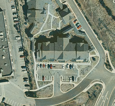
Color Digital Orthophotography (1 foot pixel)
Overall Lessons Learned
Throughout any large project there are lessons to be learned. Most of the lessons that were learned from this project have already been provided in this paper. This section highlights the more significant ones.
Management Planning
A very important thing is to have good management in place during the entire conversion process on both the vendor side and the client side. Inadequate management or changes in management can jeopardize the success of the project. Management needs to make decisions and stick to them. There are a lot of aspects that need to be overseen and the project managers must be on top of all of them. Particularly on large projects, an experienced and trained project manager is essential for successful completion (from the client's data perspective and the vendor's bottom line perspective).
QA/QC Planning
QA/QC is one of the most important aspects of the data conversion effort. You can pay a lot of money to have your data converted but if it is wrong it is no good. Having an independent QC vendor checking your data is strongly recommended. Having the QC vendor on site is preferable since their staff will have quick access to source data and knowledgeable staff. The other aspect of this is having automated checking routines, particularly for cadastral data. Since there is so much information that is being converted it can't all be checked manually. Setting up automated routines to do most of the checking saves time and eliminates much of the human error that can occur looking at data. Automated checking also readily provides data for statistical analysis and tracking. There still is the need to look at the data to ensure it is correct but to a lot lesser degree.
Communications Planning
Communication is vital in a large project such as this one. Misunderstandings can lead a conversion project down the wrong path quickly. Plan on having many meetings and drawing lots of pictures. Ask a lot of questions to get everything out on the table. It is good to ask any and all questions at each meeting in order to get all the information. Writing up the minutes of all meetings and sharing them with all that attended is essential to ensure that everyone agrees with what was said. It is also advisable to have weekly or twice weekly status phone calls. During these any issues that had come up in the previous few days could be addressed immediately and not wait for a regularly scheduled face to face meeting.
Resource Planning
In a project of this magnitude it is very important to have enough resources to complete the project. The data conversion vendor needs to have enough staff at all times during the project to convert the data and to make corrections when they are called. The county needs to have enough staff available to scrub the source materials and review the incoming data for acceptance. If there is not enough resources this can slow the project down and deadlines will be missed.
References
[1] Project Management Institute, Project Management Body of Knowledge, pmbok guide, (1996).
[2] The American Society for Photogrammetry and Remote Sensing, ASPRS Accuracy Standards for Large-Scale Maps, (1990).
Author Information
Greg Thomas
GIS Database Administrator
Fairfax County
12000 Government Center Parkway
Suite 117
Fairfax, Virginia 22035
(703) 324-2283
(703) 324-3937 fax
gregory.thomas@co.fairfax.va.us
Neal Millett
Project Manager
Analytical Surveys, Incorporated
1935 Jamboree Drive
Suite 100
Colorado Springs, Colorado 80920
(719) 264-5527
(719) 528-5093 fax