By: John Ennis, Paul F. Boulos, J. Erick Heath, and Paul Hauffen
MW Soft, Inc.
300 North Lake Avenue, Suite 1200
Pasadena, CA 91101 USA
Geographic information system (GIS) is a tool that is quickly becoming a valuable management asset to many water utilities. Simply used as a spatial database, GIS can greatly assist in various modeling applications through the development of automated tools for constructing and maintaining reliable hydraulic network models of water distribution systems. This paper presents a comprehensive decision support system (H2OMAP) for use in the effective management of water distribution systems. The software system links an advanced hydraulic network simulator with geographic information system technology for spatial database management and graphical display and analysis of results. The graphical interface is developed using MapObjects technology and provides an informative structured framework for network model construction, analysis, and result presentation. The resulting software offers a virtual environment to assist decision makers in formulating, evaluating and screening competing management strategies.
Computer simulation models of water distribution systems represent the most effective and viable means for evaluating system response to various management strategies. To be effective these models require extensive spatial and hydraulic infrastructure data readily available from GIS. GIS is unique in its ability to capture, store and manage spatially referenced data required by the network model and its applications. It provides functions for development and preparation of pertinent spatial information for input to network models as well as functions to facilitate graphical output display for evaluating results. Visualization can also be supplemented by spatial and aspatial queries of model results to help identify correlation between input parameters and model results. Therefore the marriage of water distribution network models and GIS is a natural development of simulation and database technology.
While many powerful water distribution modeling software exist, few are currently integrated with GIS software. Engineers, used to working in the CAD environment, have grown increasingly dependent on its usability and interface design. Likewise, enterprise GIS software has not been tailored, both in terms of price and functionality, to serve the requirements of water distribution system analysis. As such, software for the analysis of water distribution systems was normally created in the CAD environment to accelerate and ensure acceptance from the engineering community. This paper presents a new and practical solution to comprehensive water distribution modeling and management that greatly facilitates the requirements of the engineer while providing the extensive functionality of a GIS. With H2OMAP1-2, the graphical interface is developed using Esri MapObjects technology and provides an informative structured framework for network model construction, analysis, and results presentation.
Water utility engineers are tasked with ensuring the safe and efficient supply of drinking water. The role of a GIS in the analysis of a distribution system is to provide accurate data for which an engineering analysis is to be carried out. However, current GIS software solutions have not adequately addressed the requirements of the engineering community since they were not designed to perform the necessary network management functionalities, from hydraulic and water quality analyses to fire flow computation, pump scheduling, and selective scenario management. As a result, engineers have relied on exporting data from GIS data sets into third party software to model, analyze, plan, and design water distribution systems. While efforts to date have proven successful in allowing very basic engineering analyses from a GIS, engineers have been reluctant to embrace and utilize this technology. .
Part of the reason for this reluctance can be attributed to the way many GIS software solutions treat network data elements. For example, a water distribution system that serves 150,000 people may have a GIS that contains anywhere from 100,000 to 250,000 separate pipe segments. Even if a GIS were able to successfully model that many elements, not many engineers are willing to wade through the massive amount of data generated from such a hydraulic simulation. Another reason may lie in the complex command structures of many GIS software packages. Again, engineers are well educated and trained in CAD solutions and are usually not willing to learn a new software package just to model a water system. Still another reason may be the computational speed of the analysis software. Engineers are used to working on the best and fastest computers available and waiting around can be quite unnerving for someone who needs to evaluate and screen multiple management strategies. One final reason may be the price point of many GIS modeling solutions. Spending upwards of $15,000 to create and run a model that is less robust and has fewer features than a $6,000 solution may prove difficult to justify, especially for many users who are tied to a fixed budget.
It is for these reasons that engineers have opted to export the necessary data from a GIS into a third party software application designed specifically for the engineering analysis of a water distribution system. Therefore, the GIS exporting process has become an accepted task among engineers and has raised some common issues among practicing modelers.
One major problem with exporting data outside of a GIS and into a third party software application for engineering analysis is the fact that a duplication of data will almost always be realized. Once this occurs it becomes very difficult to ensure data integrity between the two distinct GIS and modeling data sets in the future. This occurs because engineering models take on a life of their own outside of a GIS3. Engineers spend hours tailoring the model to match existing field conditions. Pumps, pressure reducing valves, storage reservoirs, wells, closed pipes, etc. are all addressed by the engineer in the hydraulic modeling software that would otherwise be disregarded by the GIS manager. The engineer also goes to great lengths to ensure data integrity for the purpose of running a hydraulic model. Pressure zone boundaries are delineated, demand area polygons are created and point loads are determined. All of these activities bring about the modification and adjustment of existing facilities as well as the creation of new facilities, further complicating the task of exchanging modeling data with the GIS.
While duplication of data is a potential risk when creating an engineering model from a GIS, a recognized advantage is finding overlooked errors in the GIS data sets. When GIS mapping was getting started, the decision for many cities was how to best go about creating the data and determining which department would be responsible for the oversight of the data creation. Many cities decided to outsource data creation and then assign the Information Systems (IS) division to oversee the contract and continue data management upon project completion. Because of outsourcing, many cities received data sets that were not thoroughly inspected for data accuracy. The Engineering/Planning and Operations departments, not realizing the future impact of these outsourcing contracts, were left out of the loop in the data generation process. Because of the combination of outsourcing and IS oversight, data integrity of a hydraulic system is usually suspect. While many cities may believe they possess a highly accurate GIS, it is only until the Engineering/Planning department, in collaboration with the Operations department, utilizes GIS data for the purpose of creating a water master plan. It is at the time of a network model development for a system-wide master plan that issues regarding pipe diameter, material, location, connectivity, node elevation, etc. are thoroughly reviewed and inspected. What many find is that the highly accurate GIS data set harbors errors that require further investigation and correction. Many master plans are delayed while data discrepancies are adjusted to reflect actual system conditions.
As previously stated, even though these errors are addressed and resolved in the hydraulic model, little is done to ensure that all of those corrections made in the modeling software application are implemented back into the GIS. In many instances, once a hydraulic model is developed for the sake of the master plan, the model is now more accurate than the GIS data used in its creation. However, an effective and efficient solution to this problem has now been realized with H2OMAP - a stand-alone hydraulic modeling software application built completely with GIS technology.
H2OMAP approaches water network modeling from a GIS-centric point of view and works to avoid the duplication effort involved in the creation of a hydraulic model. Built entirely with Esri MapObjects technology, H2OMAP uses Shapefile as its native data format. This means that as pipes and nodes are created in the application, they are also stored externally to the program as Shapefiles, ready to be viewed by any other third party GIS application. The product is entirely different than any other hydraulic modeling application because of its extensive use of GIS standards. The following example has been provided to demonstrate how H2OMAP reduces errors and facilitates model creation.
A city has decided to undertake a water master plan. Using the city GIS water coverage, the GIS department assigns a unique value to each water facility in the GIS. The data is then saved as a Shapefile and imported into H2OMAP. The engineer then works on the data, assigning pump characteristic curves, tank levels, valve settings, pipe roughness coefficients, etc. In the process, the engineer rectifies connectivity issues and assigns facilities to their appropriate pressure zone using the Domain Manager function of H2OMAP. The engineer proceeds to work on the hydraulic model, rectifying problem areas and building the hydraulic model. Since the data is automatically stored as Shapefiles, the GIS manager views the H2OMAP data in the GIS program and updates the changes made by the engineer without ever having to ask for the updates. The GIS manager may also chose to replace his facilities with those from the hydraulic model, as they are now more accurate and contain additional data values not stored in the GIS.
Because data sets are stored as Shapefiles, anyone in the organization can view the hydraulic model outside of H2OMAP. Pipes, pumps, valves, tanks, etc. can be added as views to ArcView GIS or as layers in AutoCAD or Microstation. Pressure contours derived from a hydraulic analysis and annotation layers for labeling the hydraulic network components and results are also stored as Shapefiles, able to be viewed at any time in GIS software packages. The functionality of H2OMAP allows engineers to analyze water distribution systems and GIS departments to integrate model data in a smooth and seamless manner.
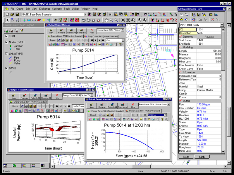
Unlike other hydraulic models, H2OMAP is a full-featured hydraulic analysis software solution. Utilities can use it for optimal pump scheduling, developing multiple modeling scenarios, analyzing system flows and pressures, performing water quality and fire flow analyses, creating pressure contours, and monitoring SCADA operations. The program is built with object-component technology to provide a powerful and practical GIS platform for water utility solutions. As a stand-alone program, it combines spatial analysis tools and mapping functions with sophisticated and accurate network analysis capabilities. Almost any GIS or CAD layer can be added to the program at any time. This includes coverages, Shapefiles, SDE layers, MID/MIF, AutoCAD and Microstation.
The open-architecture framework makes it easy to manage and distribute geospatial data as well as exchange important modeling information with other applications and enterprise systems. Again, because it accesses and stores internal data in Shapefile format, H2OMAP instantly becomes an integral part of the enterprise. Users can develop informed GIS solutions to help them meet and exceed drinking water quality standards, optimize system performance, determine capital improvements, enhance operations, and achieve customer satisfaction in a timely manner and efficient manner.
H2OMAP offers all the capabilities an organization demands from a state-of-the-art hydraulic network solver. Real-time simulations, hydraulic optimization, water quality analysis, fire fighting flow determination, calibration, energy analysis, as well as determining unidirectional flushing programs are just a few of the features.
Another important feature is the rule-based logical control technology which allows for precise simulation of the hydraulic behavior of a water system and automatically controls the status of data elements based on time of day, tank water levels, node pressures, pump flow rates or any combination of factors. This feature is critical for anyone wishing to evaluate the operational efficiency of a hydraulic system over an extended period simulation.
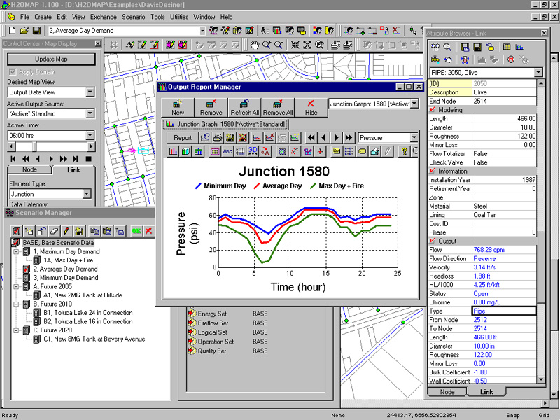
H2OMAP's comprehensive scenario manager allows for the rapid development and evaluation of multiple modeling scenarios with different network topological configurations and physical facility characteristics, as well as external demand loading and operating conditions, while benefiting from a multi-level inheritance among the selected scenarios. Every change made to any "parent" scenario is reflected through the entire set of "child" projects in an easy-to-use, tree-like structure, allowing the user to switch between scenarios, merge models, and compare results instantly while giving a clear illustration of system behavior to different conditions and planning horizons.
H2OMAP provides sophisticated network analysis and simulation capabilities for performing a wide range of essential modeling tasks. It utilizes a full-featured, state-of-the-art hydraulic computational engine that includes the following capabilities:
places no limit on the size of the network and number of components that can be analyzed (unlimited link version)
supports both English and metric (Standard International) units
analyzes steady-state and extended period simulations
computes friction headloss using the Hazen-Williams, Darcy-Weisbach, or Chezy-Manning formulas
includes minor (local) head losses for bends, meters, fittings, etc.
models constant or variable speed pumps
models turbines and flow totalizers (meters)
calculates Net Positive Suction Head requirements (available NPSH, required NPSH, and cavitation index) to ensure cavitation free operation
determines system head curves and fire hydrant rating curves
calculates available and design fire flows at minimum residual pressures
computes pumping energy and cost based on variable electricity and demand charges
accommodates various types of static and control valves including shutoff, check, float, pressure regulating, pressure sustaining, pressure beaker, motorized throttle control, general purpose, and flow control valves
allows single and multiple inlet/outlet storage tanks to have any shape (i.e., diameter can vary with height)
models constant and variable head reservoirs
considers multiple demand categories at nodes, each with its own pattern of time variation
models pressure-dependent demand issuing from emitters (sprinkler heads)
automatically carries out pressure-demand analysis to compute the % of demand supplied to each node (ratio of actual demand versus specified demand)
tracks flow reversals for pipe flushing
simulates leakage in a pipe
specifies system operation based on both simple node pressure, tank level, link flow, or timer controls and on complex rule-based controls
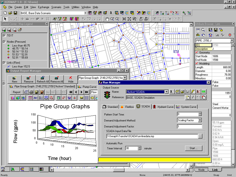
provides SCADA interface with alarms.
H2OMAP provides fast, comprehensive and accurate dynamic water quality computations in the following ways. It:
tracks the movement of a non-reactive tracer material (e.g., fluoride) through the network over time
models the movement and fate of a reactive material as it grows (e.g., a disinfection by-product) or decays (e.g., chlorine residual) with time
calculates the age of water throughout a network
computes the percent of flow from a given node reaching all other nodes over time
analyzes kinetic reactions both in the bulk flow and at the pipe wall
incorporates n-th order kinetics to model reactions in the bulk flow
uses zero or first order kinetics to model reactions at the pipe wall
accounts for mass transfer limitations when modeling pipe wall reactions
allows growth or decay reactions to proceed up to a limiting concentration
employs global reaction rate coefficients that can be modified on a pipe-by-pipe basis
permits wall reaction rate coefficients to be correlated to pipe roughness
allows for time-varying concentration or mass inputs at any location in the network
models storage tanks as being either complete mix, plug flow, or two-compartment reactors.
Interfacing with GIS applications is a very reliable and efficient means of developing hydraulic network models of water distribution systems. However, because GIS facilities are typically created for Automated Mapping/Facilities Management (AM/FM) applications (e.g., water distribution system maintenance and management), this format is generally not suitable for construction of hydraulic network models. Common data format problems encountered by practicing modelers are inclusion of hydrants, line valves, and tees or crosses.
H2OMAP greatly simplifies and reduces large GIS models to a manageable size ready for hydraulic analysis. It expeditiously processes detailed GIS data and efficiently constructs reliable water system network models using three automated applications. These are: data reduction (Reduce), skeletonization (Skeletonize), and trimming (Trim) applications (or RST applications).
Data reduction application is the capability to remove excessive pipe segmentation caused by valves, fire hydrants or other data capture processes, by dissolving interior nodes on pipe reaches and combining the associated pipe segments into single pipes. For example, merging all series pipes of similar diameter, material and age. Data skeletonization application refers to the capability of removing all pipes with diameters less than a specified value (e.g., removing all 250 mm and smaller pipes). Data trimming application designates the capability to remove short pipe segments such as dead ends and hydrant leads. Trimming is carried out on only those pipes possessing at least one node of degree one, where the degree of a node is the number of pipes connected to it.
RST applications are functions readily available that can be effectively used to convert GIS data into a hydraulic model.
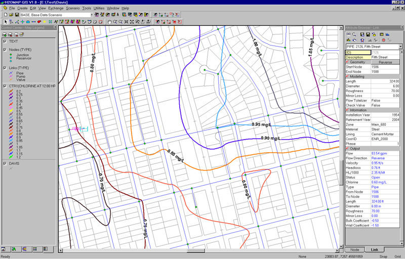
Using powerful GIS thematic mapping functionality, H2OMAP makes it easy to turn dry database information into stunningly colorful, fully dimensional visualizations and to present analysis results in map form. Users can generate accurate, and smooth contours for any variable including elevation, pressure, hydraulic grade line, demand, water age, chlorine concentration, and more, directly on the map- even overlay multiple contours on a single drawing. Users can also draw on a range of other sophisticated graphical presentation tools, including color-coded mapping, dynamic annotation/labeling, graphing, profiling, customizable tabular reporting, and vivid VCR-style animation to produce truly compelling results. These graphical capabilities are critical to better communicate and understand problem areas and system deficiencies and to present remedial engineering solutions at community information sessions or council meetings.
Water utility engineers are discovering a wide variety of uses for GIS technology. In particular, GIS information is critical to water distribution system analysis. H2OMAP has been presented as a decision support system to provide a GIS-based solution for water distribution system modeling and management. Built entirely with MapObjects technology, H2OMAP integrates GIS functionalities with a hydraulic network simulator allowing accurate network model construction and providing a reliable and effective means for decision makers to quickly assess and address the implications of alternative design, rehabilitation and operational changes on system performance. Through the exploitation of GIS graphical data visualization capabilities potential system deficiencies can be quickly identified where improvements are required. The resulting GIS-enabled software allows a wide range of potential network improvement and enhancement alternatives to modeled, analyzed, contrasted, and evaluated, providing water utility managers with the ability to readily optimize their capital improvement programs. It also makes it easy for any utility to work seamlessly, across platforms and to manage water systems in a single, stand-alone software environment.
1. H2OMAP - Users Guide (2001). MW Soft, Inc. 300 North Lake Avenue, Suite 1200, Pasadena, CA 91101.
2. H2OMAP Skeletonizer - Users Guide (2001). MW Soft, Inc, 300 North Lake Avenue, Suite 1200, Pasadena, CA 91101
3. Miles, S.B and Ho, C.L. (1999). "Applications and Issues of GIS as Tool for Civil Engineering Modeling." Journal of Computing in Civil Engineering ASCE, Vol. 13, No. 3, pp. 144-152.


