An ArcView GIS Extension for Interpreting and
Delineating Features in Georeferenced Imagery
Kenneth Buja
Matt Kendall
Abstract
NOAA's Biogeography Team has developed an ArcView extension to simplify the
task of delineating features from georeferenced imagery using heads up digitizing.
The extension allows a user to dynamically build a classification scheme or
load and make modifications to an existing scheme. The extension creates a shapefile
containing the necessary fields for the classification scheme attributes with
the click of a button. The extension contains tools to add, append, and split
polygons, which are then attributed with a classification type selected with
dialogs. Additional tools can be used to set a minimum polygon size and scale
restriction for digitizing.
Background
NOAA's Biogeography Team is leading a project to consistently and comprehensively map the distribution of coral reefs and other benthic habitats throughout the US Virgin Islands and Puerto Rico. Aerial photographs are being used to create a digital map of the marine resources in the region including coral reefs, seagrass beds, mangrove forests, and other important marine resources for fisheries, tourism, and other aspects of the coastal economy. The primary product of this effort will be benthic habitat maps, created using visual interpretation of scanned aerial photographs.
A similar project was conducted to map the benthic habitat of the Florida Keys. However, this project took five years using three photo-interpreters, two compilerers, and an Arc/Info specialist. The interpreters traced and attributed polygons on acetate overlays on the hard copy photography. The compilerers used a stereoplotter to create Arc/Info files using the hand-drawn overlays, while the specialist edge matched the Arc/Info files. This method proved to be cumbersome, with error introduced into the work at many possible stages.
In an effort to maximize the efficacy of the process for the Caribbean benthic mapping project, the interpretation work was done using heads up digitizing and mosaiced digital imagery. The aerial photography was geo-referenced and orthorectified, with the best segments of each photo being selected for creation of the final mosaics. Since the interpreter doing the heads up digitizing had little previous experience with ArcView, an extension was designed and written to simplify polygon delineation and automate the attribution process. The extension was written with a hierarchical habitat classification scheme specific to the Caribbean region and hardwired into the attribute selection process. With this new extension, the benthic habitats were mapped three times faster than in the Florida Keys project, resulting in a product with significantly greater spatial and thematic accuracy.
A second project was initiated to map the benthic habitat of the Hawaiian Islands, requiring a different classification scheme. Rather than writing another extension with a unique classification scheme hardwired into it, the extension was generalized to allow different classification schemes, both terrestrial and marine, to be added by a user, significantly expanding its usefulness to the interpretation community.
On-Screen Mapping with ArcView’s Habitat Digitizer
The habitat digitizer extension to ArcView 3.1 was developed to facilitate mapping benthic habitats of Puerto Rico and the U.S. Virgin Islands. The extension was originally created to map habitats using this scheme by visually interpreting orthorectified aerial photos. The extension’s capabilities have been expanded to allow users to map from other georeferenced image data such as satellite images and side scan sonar. The extension allows users to rapidly delineate and attribute polygons using simple menus. It also allows new hierarchical classification schemes to be easily created, modified, and saved for use on future mapping projects.
The extension is available over the internet at http://biogeo.nos.noaa.gov/products/apps/digitizer/.
The extension and accessory files can be downloaded as a Zip file. This file
contains three files including:
habitat.avx the extension
coral.hcs a classification scheme for tropical marine habitats
coral.avl an example legend for the coral.hcs classification scheme
Hardware and Software Requirements
The habitat digitizer extension is compatible with ArcView 3.1 and requires hardware similar to that recommended for proper operation of ArcView. Additional memory may enhance performance for handling large image files. The appropriate Image Support extension (TIFF, MrSID, etc.) is required depending on the format of the image files used. The Image Analyst extension is not necessary, but is recommended to facilitate manipulation of image brightness, contrast, and color balance.
Getting started
To begin using Habitat Digitizer, save the habitat.avx file in either ArcView’s Ext32 directory or the USEREXT directory. The coral.hcs and coral.avl files can be saved anywhere, but they should preferably be placed in the ArcView project’s working directory.
After starting ArcView, load the Habitat Digitizer Extension (and any other desired extensions) by selecting "File/Extensions…" and click on the box next to the Habitat Digitizer Extension in the "Available Extensions" list. Click "OK" to install the extension. If a project already exists that used the Habitat Digitizer Extension, opening the project will automatically load the extension.
Setting the Projection Parameters for the Image Data:
The Habitat Digitizer enables users to specify a minimum mapping unit (MMU), digitizing scale, and offers several other spatial functions that require the View’s projection and map unit’s to be set properly. The projection properties of the View must be set to those of the image data from which habitats are being interpreted. Once the View’s projection is set properly, shapefiles created using Habitat Digitizer will be unprojected (in decimal degrees). To set the projection properties, select View/Properties and set the map and distance units as well as the Projection information of the image. If this information is not set, the shapefile will be created in the projection coordinates of the image files (not in decimal degrees) and the MMU, scale restriction, and other spatial functions of the extension will not work.
The Habitat Digitizer Menu
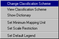 Once
the Habitat Digitizer Extension has been activated the Habitat Digitizer
pull-down menu and digitizing tools which control the functions of the extension
will appear on the ArcView toolbar. Beginning with the process of creating and
loading classification schemes, a detailed description and instructions for
each function in the extension are provided below.
Once
the Habitat Digitizer Extension has been activated the Habitat Digitizer
pull-down menu and digitizing tools which control the functions of the extension
will appear on the ArcView toolbar. Beginning with the process of creating and
loading classification schemes, a detailed description and instructions for
each function in the extension are provided below.
Creating a new classification scheme
Unless an existing classification scheme such as coral.hcs is used, a new scheme must first be created to use the extension. Before creating a new scheme using the dialogs of the extension, it may be useful to sketch the scheme out on paper to ensure that all fields and categories in the hierarchy are entered properly. There are several advantages to using a scheme with a hierarchical structure including: the detail of habitat categories can be expanded or collapsed to suit user needs, the thematic accuracy of each category/hierarchical level can be determined, and additional categories can be easily added or deleted at any level of the scheme to suit user needs. An example of a scheme framework is provided in Table 2.1 below.
Table 2.1: Example Classification Scheme Framework
|
Field 1 |
Field 2 |
Field 3 |
Field 4 |
UniqueID |
|
Category 1 |
Subcategory 1 |
Subcategory 1 |
(empty) |
111 |
| |
|
Subcategory 2 |
|
112 |
| |
Subcategory 2 |
Subcategory 1 |
|
121 |
| |
|
Subcategory 2 |
|
122 |
|
Category 2 |
Subcategory 1 |
Subcategory 1 |
|
221 |
| |
|
Subcategory 2 |
|
222 |
| |
Subcategory 2 |
|
|
22 |
|
Category 3 |
Subcategory 1 |
|
|
31 |
| |
Subcategory 2 |
|
|
32 |
 To
create the new scheme using the extension, select Habitat Digitizer/Change
Classification Scheme and in the next dialog box, select Create New Scheme.
Type the name of the new classification scheme in the message box and click
Okay. The other options in this dialog will be unavailable until a scheme
has been either created or loaded.
To
create the new scheme using the extension, select Habitat Digitizer/Change
Classification Scheme and in the next dialog box, select Create New Scheme.
Type the name of the new classification scheme in the message box and click
Okay. The other options in this dialog will be unavailable until a scheme
has been either created or loaded.
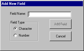 In
the Add New Field dialog, selecting Cancel will end the creation
process without creating a scheme. Once the first field name has been added,
this button is replaced with the Finished button, which will complete
the field naming process and go to the next step in creating the scheme. First,
type in the field name for the most general hierarchical level in the new classification
scheme (Field 1 in Table 2.1). Field names are limited to 10 characters in length.
Select whether the field will be character or numeric and click Add Field.
Add additional field names in the order of the classification hierarchy. A fieldname
must be entered for every level in the hierarchy. Because new fields cannot
be added after the scheme creation process is closed, add a few extra fields
as placeholders in case any additional unforeseen levels in the hierarchy are
required at a later time. After all the field names have been entered select
Finished to proceed to the next step. Once Finished is selected,
no additional fields may be added to the classification scheme. Note that a
field named UniqueID is added automatically after Finished is
selected.
In
the Add New Field dialog, selecting Cancel will end the creation
process without creating a scheme. Once the first field name has been added,
this button is replaced with the Finished button, which will complete
the field naming process and go to the next step in creating the scheme. First,
type in the field name for the most general hierarchical level in the new classification
scheme (Field 1 in Table 2.1). Field names are limited to 10 characters in length.
Select whether the field will be character or numeric and click Add Field.
Add additional field names in the order of the classification hierarchy. A fieldname
must be entered for every level in the hierarchy. Because new fields cannot
be added after the scheme creation process is closed, add a few extra fields
as placeholders in case any additional unforeseen levels in the hierarchy are
required at a later time. After all the field names have been entered select
Finished to proceed to the next step. Once Finished is selected,
no additional fields may be added to the classification scheme. Note that a
field named UniqueID is added automatically after Finished is
selected.
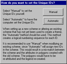 The
extension uses the UniqueID field to identify each possible combination
of hierarchical categories with one unique number (see Table 2.1). ArcView uses
uniqueIDs to link polygon attributes to the legend. The dialog at left sets
the method of assigning uniqueIDs. When setting up a new scheme or altering
an existing scheme that has not yet been used to create a theme, the Automatic
method should be used. The Automatic method creates a logical numbering
sequence for each uniqueID (see Table 2.1). When modifying a scheme that has
already been used to create a theme, use the Manual method. If Automatic
was used, new uniqueID’s would be assigned to the scheme, creating a mis-match
between the ID’s of the new scheme and those of the polygons attributed using
the old scheme.
The
extension uses the UniqueID field to identify each possible combination
of hierarchical categories with one unique number (see Table 2.1). ArcView uses
uniqueIDs to link polygon attributes to the legend. The dialog at left sets
the method of assigning uniqueIDs. When setting up a new scheme or altering
an existing scheme that has not yet been used to create a theme, the Automatic
method should be used. The Automatic method creates a logical numbering
sequence for each uniqueID (see Table 2.1). When modifying a scheme that has
already been used to create a theme, use the Manual method. If Automatic
was used, new uniqueID’s would be assigned to the scheme, creating a mis-match
between the ID’s of the new scheme and those of the polygons attributed using
the old scheme.
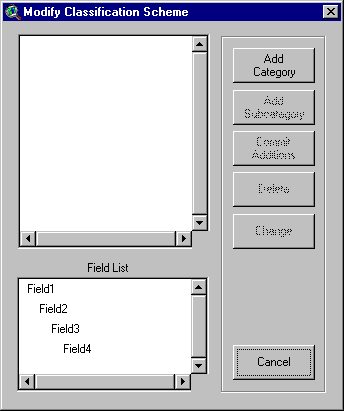
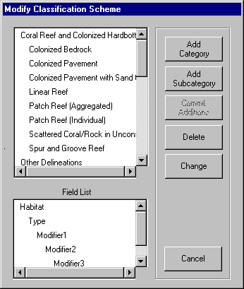
In the Modify Classification Scheme dialog, categories and subcategories
can be added to a new or existing classification scheme. Begin by adding a category
to the most general level in the classification hierarchy (Category 1 in Table
2.1). Click Add Category, then type the category name and click Okay.
Additional categories at this level in the hierarchy can be added in this way.
Adding a category at this level will activate the Add Subcategory button.
Subcategories are added within individual categories by selecting the category
of interest then clicking Add Subcategory and completing the dialog boxes.
If the uniqueIDs are to be assigned using the Automatic option
(previous dialog), the Delete and Change buttons are activated
and can now be used to modify category names. In the Automatic method,
clicking the Finished button will assign a uniqueID to each classification
combination. If Manual was selected, the Delete and Change
buttons will not be activated until the UniqueIDs for each of the categories
and subcategories have been added (next dialog). To add uniqueIDs manually,
click the Commit Additions button after all categories and subcategories
have been added, then complete the Add Unique ID dialogue box as described
below. Once the uniqueIDs have been assigned the Delete and Change
buttons will be activated. If the Cancel button is selected, the scheme
creation process will end without creating a scheme.
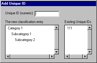 If
Manual was selected for assigning uniqueIDs, the Add Unique
ID dialog will appear after selecting Commit Additions. A unique
numeric identifier must be entered for each possible combination of classifications
in the hierarchy. The Existing Unique IDs list shows which numbers are
already used in the scheme. Duplicate numbers cannot be added. See Table 2.1
or the coral.hcs scheme that is included with the extension to get suggestions
on how to assign uniqueIDs. Once uniqueIDs are set through either
the Manual or Automatic method and Finished is selected
in the Modify Classification Scheme dialog, the new scheme can be saved
and used to digitize habitats.
If
Manual was selected for assigning uniqueIDs, the Add Unique
ID dialog will appear after selecting Commit Additions. A unique
numeric identifier must be entered for each possible combination of classifications
in the hierarchy. The Existing Unique IDs list shows which numbers are
already used in the scheme. Duplicate numbers cannot be added. See Table 2.1
or the coral.hcs scheme that is included with the extension to get suggestions
on how to assign uniqueIDs. Once uniqueIDs are set through either
the Manual or Automatic method and Finished is selected
in the Modify Classification Scheme dialog, the new scheme can be saved
and used to digitize habitats.
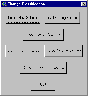
Saving, Re-Loading, and Creating Scheme Legends
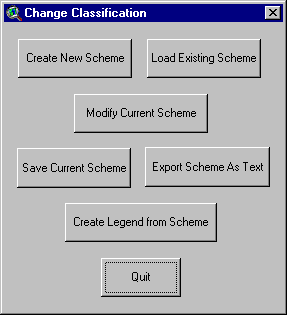 Once
finished creating or modifying a scheme, save the scheme to a file by selecting
Save Current Scheme in the Change Classification dialog box. The
file will be saved as a *.hcs (habitat classification scheme) file. To access
this scheme, select Load Existing Scheme in the Change Classification
dialog box. A file selection dialog will open showing only the *.hcs files.
Additional options that can be used at this time include the Export Scheme
As Text button which will create a text file showing the hierarchical structure
of the scheme, and the Create Legend from Scheme button which will create
a legend that contains each uniqueID and its attributes. Legend labels
will have all of the categories in the classification hierarchy concatenated
into one string. Colors will be randomly selected and an additional Unclassified
category will be added with a uniqueID of zero.
Once
finished creating or modifying a scheme, save the scheme to a file by selecting
Save Current Scheme in the Change Classification dialog box. The
file will be saved as a *.hcs (habitat classification scheme) file. To access
this scheme, select Load Existing Scheme in the Change Classification
dialog box. A file selection dialog will open showing only the *.hcs files.
Additional options that can be used at this time include the Export Scheme
As Text button which will create a text file showing the hierarchical structure
of the scheme, and the Create Legend from Scheme button which will create
a legend that contains each uniqueID and its attributes. Legend labels
will have all of the categories in the classification hierarchy concatenated
into one string. Colors will be randomly selected and an additional Unclassified
category will be added with a uniqueID of zero.
Editing an existing classification scheme
 To
edit an existing scheme, select Modify Current Scheme in the Change
Classification dialog box. After selecting the method of assigning the uniqueID
(in this case, using Manual is recommended), the Modify Classification
Scheme dialog appears. Follow the same instructions in Creating a new
scheme to edit this scheme using the dialog at left.
To
edit an existing scheme, select Modify Current Scheme in the Change
Classification dialog box. After selecting the method of assigning the uniqueID
(in this case, using Manual is recommended), the Modify Classification
Scheme dialog appears. Follow the same instructions in Creating a new
scheme to edit this scheme using the dialog at left.
Digitizing Restrictions
Minimum Mapping Unit
Depending on the quality of aerial images used and the specific goals of the
project, it is often desirable to limit the minimum size of the features that
are delineated. For example, poor image resolution may preclude the interpretation
of features smaller than some minimum size threshold. Other features, while
interpretable in the imagery, may simply be too small and therefore beyond the
scope or goals of the desired map product. To limit the size of the features
that can be digitized in the habitat map, a minimum mapping unit (MMU) can be
set in Habitat Digitizer. Features must be larger than the MMU to be included
in the habitat map.
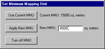 Set
the MMU restriction by selecting Habitat Digitizer/Set Minimum Mapping Unit.
If the view’s map and distance units are set, a dialog will appear
showing the current MMU. Enter the desired numerical MMU into the text box and
select Apply New MMU. If a satisfactory MMU has already been set, Use
Current MMU will close the dialog without changing the MMU. Once an MMU
is set, if the area of a newly digitized polygon is below the value specified,
a message box will ask whether the polygon should be added to the theme. If
no MMU restriction is desired, Habitat Digitizer/Set Minimum Mapping Unit/Turn
off MMU will allow digitizing polygons with no size restriction.
Set
the MMU restriction by selecting Habitat Digitizer/Set Minimum Mapping Unit.
If the view’s map and distance units are set, a dialog will appear
showing the current MMU. Enter the desired numerical MMU into the text box and
select Apply New MMU. If a satisfactory MMU has already been set, Use
Current MMU will close the dialog without changing the MMU. Once an MMU
is set, if the area of a newly digitized polygon is below the value specified,
a message box will ask whether the polygon should be added to the theme. If
no MMU restriction is desired, Habitat Digitizer/Set Minimum Mapping Unit/Turn
off MMU will allow digitizing polygons with no size restriction.
Scale Restriction
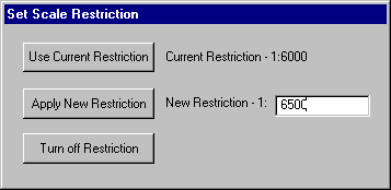 It
is possible to adjust the scale of the image files as they appear on the computer
monitor. For example, the scale of hard copy photographs used for mapping may
be 1:48000, however the actual photo interpretation may be conducted on the
computer monitor while zoomed in on the scanned photographs at a much larger
scale (e.g.1:6000). It is often desirable to conduct all polygon delineation
at the same scale, so that all polygons have the same level of detail. Set the
scale restriction by selecting Habitat Digitizer/Set Scale Restriction.
Enter a number in the text box and select Apply New Restriction. If digitizing
is attemped while a scale restriction is in place and the view is not at the
specified scale, a message box will appear and offer to zoom the view to the
proper scale. If No is selected, a polygon cannot be digitized. If a
scale restriction is not desired, use Habitat Digitizer/Set Scale Restriction/Turn
off Restriction to allow digitizing at any scale. The view’s map
and distance units must be set to use this tool.
It
is possible to adjust the scale of the image files as they appear on the computer
monitor. For example, the scale of hard copy photographs used for mapping may
be 1:48000, however the actual photo interpretation may be conducted on the
computer monitor while zoomed in on the scanned photographs at a much larger
scale (e.g.1:6000). It is often desirable to conduct all polygon delineation
at the same scale, so that all polygons have the same level of detail. Set the
scale restriction by selecting Habitat Digitizer/Set Scale Restriction.
Enter a number in the text box and select Apply New Restriction. If digitizing
is attemped while a scale restriction is in place and the view is not at the
specified scale, a message box will appear and offer to zoom the view to the
proper scale. If No is selected, a polygon cannot be digitized. If a
scale restriction is not desired, use Habitat Digitizer/Set Scale Restriction/Turn
off Restriction to allow digitizing at any scale. The view’s map
and distance units must be set to use this tool.
Creating a theme and using the digitizing tools
 Once
a classification scheme has been loaded, this button creates an empty theme
with the appropriate fields. If a default legend has not been created using
Habitat Digitizer/Set Default Legend or the Change Classification
dialog, a dialog will appear to select a legend file. A second message box will
appear asking if this legend should be made the default legend for all new themes
created using this classification scheme. After creating a new theme, set the
snapping tolerance by using the menu selection Theme/Properties and in
the Editing selection, click the General box and set the tolerance
to a number smaller than the pixel size of the images used for interpretation
(since no interpretation will presumably be conducted within pixels). If this
is not done, adjacent polygons will not always share a common border.
Once
a classification scheme has been loaded, this button creates an empty theme
with the appropriate fields. If a default legend has not been created using
Habitat Digitizer/Set Default Legend or the Change Classification
dialog, a dialog will appear to select a legend file. A second message box will
appear asking if this legend should be made the default legend for all new themes
created using this classification scheme. After creating a new theme, set the
snapping tolerance by using the menu selection Theme/Properties and in
the Editing selection, click the General box and set the tolerance
to a number smaller than the pixel size of the images used for interpretation
(since no interpretation will presumably be conducted within pixels). If this
is not done, adjacent polygons will not always share a common border.
 To
start digitizing a new polygon, select this tool and trace the feature of interest
by clicking around its perimeter with the mouse. A double click closes each
new polygon. If a polygon is digitized inside or completely around an existing
polygon, "donut" and "donut hole" polygons will be formed.
Once the polygon is complete, a message box will allow the classification to
be set as outlined below.
To
start digitizing a new polygon, select this tool and trace the feature of interest
by clicking around its perimeter with the mouse. A double click closes each
new polygon. If a polygon is digitized inside or completely around an existing
polygon, "donut" and "donut hole" polygons will be formed.
Once the polygon is complete, a message box will allow the classification to
be set as outlined below.
 Use
this tool to add a polygon adjacent to an existing polygon. To create a polygon
using this tool, start tracing a line inside of an existing polygon and end
the line by clicking twice inside of the same or another existing polygon. This
tool will not work when attempting to digitize a polygon inside of another polygon
(use the Split tool below to do that). The scale restriction and MMU
also apply to this tool. If several polygons are created with a single line
and some are below the MMU, a warning message will appear. If No is selected
on the warning message only the polygons that fall below the MMU will be removed.
Use
this tool to add a polygon adjacent to an existing polygon. To create a polygon
using this tool, start tracing a line inside of an existing polygon and end
the line by clicking twice inside of the same or another existing polygon. This
tool will not work when attempting to digitize a polygon inside of another polygon
(use the Split tool below to do that). The scale restriction and MMU
also apply to this tool. If several polygons are created with a single line
and some are below the MMU, a warning message will appear. If No is selected
on the warning message only the polygons that fall below the MMU will be removed.
Once polygons are completed using the Add and Append tools, a
dialog will appear to guide assignment of classification attributes.
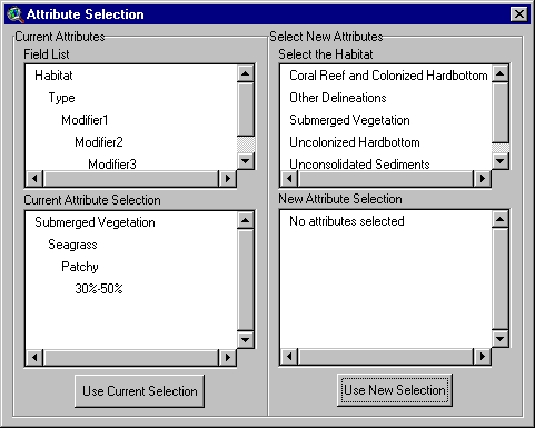 The
Field List displays the hierarchical structure of the fields in the scheme.
Current Attribute Selection shows the classification type, if any, currently
selected. Either select Use Current Selection or select a new classification
type by clicking through the desired classification attributes in the Select
New Attributes window. As new attributes are selected they will be displayed
in the New Attribute Selection window. The Use New Selection button
will be activated when the attribute in the lowest hierarchical level for the
new classification is selected.
The
Field List displays the hierarchical structure of the fields in the scheme.
Current Attribute Selection shows the classification type, if any, currently
selected. Either select Use Current Selection or select a new classification
type by clicking through the desired classification attributes in the Select
New Attributes window. As new attributes are selected they will be displayed
in the New Attribute Selection window. The Use New Selection button
will be activated when the attribute in the lowest hierarchical level for the
new classification is selected.
 This
tool splits one or more polygons into several polygons. All of the attribute
information for the resulting polygons will be the same as the original(s),
but can be changed as explained below under "Tools from the Right Mouse
Button". Please note that due to a bug in ArcView, this tool sporatically
works when attempting to split along the inside border of a donut polygon. The
scale restriction and MMU also apply to this tool. If several polygons are split
and some of the resulting polygons fall below the MMU, choosing No will
remove the entire line and merge the split polygons back together.
This
tool splits one or more polygons into several polygons. All of the attribute
information for the resulting polygons will be the same as the original(s),
but can be changed as explained below under "Tools from the Right Mouse
Button". Please note that due to a bug in ArcView, this tool sporatically
works when attempting to split along the inside border of a donut polygon. The
scale restriction and MMU also apply to this tool. If several polygons are split
and some of the resulting polygons fall below the MMU, choosing No will
remove the entire line and merge the split polygons back together.
 This
tool places a MMU sized red box on the view by clicking the button and then
clicking directly in the View at the desired location. This box enables users
to estimate the size of features in the imagery relative to the MMU. This box
disappears when panning, zooming in or out, or after completing a polygon. To
use this feature while adding a new polygon see "Tools from the Right Mouse
Button" below.
This
tool places a MMU sized red box on the view by clicking the button and then
clicking directly in the View at the desired location. This box enables users
to estimate the size of features in the imagery relative to the MMU. This box
disappears when panning, zooming in or out, or after completing a polygon. To
use this feature while adding a new polygon see "Tools from the Right Mouse
Button" below.
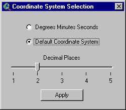
 This
tool brings up a dialog to display the cursor’s x/y position in the upper right
hand corner of the ArcView window in either the coordinate system of the view
(default) showing from 1-5 significant digits, or in degrees, minutes, and seconds.
This requires that the view’s projection be set and the map units specified.
This
tool brings up a dialog to display the cursor’s x/y position in the upper right
hand corner of the ArcView window in either the coordinate system of the view
(default) showing from 1-5 significant digits, or in degrees, minutes, and seconds.
This requires that the view’s projection be set and the map units specified.
Tools from the Right Mouse Button
Click and hold down the right mouse button to view a list of additional tools
and options:
Panning will recenter the display over the spot where the right mouse
button was clicked. This is useful while digitizing large polygons that do not
fit entirely within the view frame.
Pan to Location will center the display at the coordinates entered in
a message box
Show attributes will display a message box showing the habitat attributes
for the currently selected polygon.
Change habitat attribute will allow the user to change the habitat attributes
for polygons that are selected.
MMU Box places an MMU box on the View where the right mouse button
was clicked (can be added while digitizing a polygon).
Polygon Area shows the area of a selected polygon.
When a project is saved, the settings (classification scheme, MMU, scale restriction,
default legend, cursor display precision, and current attribute selection) will
be stored along with the project. Upon opening the saved project, these settings
will be restored and do not need to be re-entered.
Kenneth Buja
Matt Kendall
Biogeography Program, Center for Coastal Monitoring and
Assessment
National Centers for Coastal Ocean Science, National Ocean Service
National Oceanic and Atmospheric Administration
1305 East West Highway, N/SCI1
Silver Spring MD 20910
(301) 713-3028 x140
Ken.Buja@noaa.gov