
The Transportation Object Platform – TOP – is a data storage and management platform developed to ease the maintenance and use of transportation related data such as network data, infrastructure data and planning data. TOP is an open and extensible object model created as an extension to the ArcGIS Geodatabase. TOP is developed using custom behavior classes in the Geodatabase making it possible to implement forced intelligent relations and rules between objects. These rules apply to all applications, which are clients of the platform. By using ArcMap to edit geographic and tabular objects, work processes are eased while the full topological complexity of any transportation related model is retained. A suite of related tools are provided for analysis, modeling and presentation purposes:
- Editing, managing and maintaining complex multi-modal network data (including physical networks, routes, time patterns, schedules, interchanges, terminals etc.)
- Add-on visualization and editing tools for complex objects such as turns and terminals, 3D visualization of timetables, tools for displaying results (e.g. bundles which use a certain network segment, sheaves between two locations and transfer patterns in a terminal)
- Tools for handling demand data (trip matrices and freight delivery tables)
- Complex analysis applications (multi modal transport models, system equilibrium assignment models, accessibility studies, timetable optimization and evaluation etc.)
- Methods for managing hierarchical versioning and scenarios.
TOP provides a strong GIS based solution for transport planning authorities, infrastructure owners, operators and their customers, as well as for application developers and consultants for such organizations.
This paper describes the design and implementation of the Transportation Object Platform (TOP). TOP is an ArcGIS extension for handling both individual and multi-modal, timetable and route based transportation data, and consists of an intelligent object model and advanced modeling and analysis tools.
Part of the background for developing TOP is the previous solutions for handling transportation data and the problems encountered with these. Experience with large-scale complex and interdependent transportation data and the advent of ArcGIS led to the conclusion, that a much better solution was both needed and possible.
Section 2 includes some background information on previous solutions for handling transportation data and a short introduction of ArcGIS. Section 3 presents a general solution for resolving issues related to handling complex transportation data. Section 4 deals with the TOP object model, and first describes the concept that fulfills the demands made in section 3, after which the process of getting from a conceptual design to the actual implemented object model is described. Section 5 shows an example of how TOP makes the editing of complex transportation data much easier. Section 6 lists some of the tools already built or currently under development using TOP.
In the following a short overview of previous approaches for handling transportation data is presented. Section 2.1 describes some aspects of how such data has previously been handled in GIS. Section 2.2 describes problems in using specialized packages for managing transportation data. The last section introduces ArcGIS, a technology that allows a combination of the better of the two worlds.
Throughout its entire existence, GIS has been used to handle transportation data – even in the earliest systems it was possible to describe transportation networks as a layer of edges, or even with a proper link-node topology. However, even for simple transportation networks, for instance a road network, a number of constraints applied: the editing environment might not support keeping the data consistent, and it was often impossible or very slow to run network algorithms directly on the GIS-data.
Using the same approach, primitive modeling of public transportation networks was attempted by building the networks using the link-node topology. However, this approach made editing and verification of the data difficult and introduced data redundancy, as route networks had to have duplicate geometry where several routes in the model followed the same physical street.
Turntables made it possible to describe turns and turn restrictions at intersections modeled as nodes. Turntables can also be used to represent changes between routes at stops in public transport systems. However, the problem of redundant data at the edge level still prevails using this approach. Furthermore, it is necessary to implement various editing tools to ensure the consistency of the data.
The experiences recounted above lead to the conclusion, that so far, it has been difficult to establish and maintain models of multi-modal transport networks in GIS. It has also proven difficult to develop even quite simple topological models with the necessary degree of generality. An aspect of this problem is that data models of multi-modal networks often are impossible to describe using earlier GIS elements exclusively. Therefore, topological elements often have to be described outside of the GIS. The functionalities to ensure coherence of stored data thereby only cover some of the network connectivity. Overall such data models can be described as 'non-intelligent', since they cannot prevent the existence of inconsistent data.
In parallel with the development of data models in GIS, GIS-like functionality has been added to specialized off-the-shelf packages for handling transportation data have had added GIS-like functionality in order to ease the management of geographic data.
However, such software often uses proprietary data formats, resulting in difficulty in using them together with other data sources and external calculation models. This makes it difficult for users to add functionality to the packages, e.g. to add new analysis tools or to adjust existing ones. Finally, there is no easy method for synchronizing data between applications that handle different aspects of a large-scale project (one example of this could be that it is difficult to combine traffic assignment models and rail simulation models).
Unlike GIS, these packages have sought to add the data models necessary to handle the network data, but not in a general form. Often the data models are tightly tied to the analysis tools in the package. In addition, tools for editing and visualizing data are often inferior to those of a GIS. In some packages, however, the data model may be described as being somewhat 'intelligent', as the software has a fair amount of support for ensuring consistency of the data.
ArcGIS is a combination of object oriented GIS and relational databases. Thus bringing inheritance between object classes and embedded intelligent behavior. Letting objects react to events is fundamental to an intelligent data model.
Storing the Geodatabase in a relational database enables relations between objects to be navigable in e.g. ArcMap. Objects can also react to events on related objects. The COM objects in ArcGIS greatly improve the network known from ARC/INFO. One of the features in the new network technology is the ability to define connectivity rules. Hence controlling which subtypes of network classes can connect to other subtypes.
The UNETRANS consortium (UCSB, Esri, the team behind TOP and others)has sought to create a data model for transportation data focusing mainly on inheritance, relations and connectivity rules. This simple data model leaves out e.g. intelligence in the objects and custom editing and visualization tools, hence not achieving ease in editing and ensured consistency in the data.
For further information about ArcGIS, refer to http://www.Esri.com.
Extensive experience in using systems such as those described in chapter 2 for large scale practical projects has led to the formulation of a list of features, which are necessary in a system, which should handle large and complex sets of data for transportation networks. The list – which is seen below – does not pretend to be exhaustive, but it probably covers the most important aspects:
1. The system should be open, i.e. its data should be accessible through publicly available APIs, such as SQL.
2. The functionality of the system should be highly customizable through the use of standard tools, so as to facilitate the easy building of applications on top of it.
3. The system’s data model should be highly customizable, for the purpose of accommodating the easy representation of the multitude of relationships inherent in complex transportation systems.
4. The system should provide flexible, extensible, intuitive and robust editing tools.
5. The system should provide robust multi-user access to its data.
6. The system should be able to handle very large amounts of data.
As it may be seen in section 2, commercially available systems for handling transportation network data has – up until now – only lived up to a few of the items on the list above. However – the advent of ArcGIS makes it possible to develop such a system within an acceptable timeframe. The remainder of this chapter discusses the overall design of such a system and some of its additional benefits.
A key element in this system will be its basic data model, which should consist of a number of ArcGIS Geodatabase classes, each of which will represent an aspect of a complex public transportation system. Examples are: route, timetable, intersection, street, railway-line, etc. The data model should also define how these classes relate to each other, like this: “A route has a collection of timetables” or “A bus route consists of a sequence of parts of roads”.
Designing this data model is very much an exercise in traditional database design. A system consisting of ArcGIS and such a data model, meets most of the requirements listed above: It can be implemented on top of an industry standard DBMS, thus meeting requirements 1, 5 & 6.
ArcGIS is built as a very large collection of fine-grained COM-objects, enabling an extreme degree of customization through the use of COM-compliant development tools, thus meeting requirement 2. The system’s data model will be designed in a way, which enables users and developers to selectively use the parts they need. Also, the flexible design of ArcGIS enables the addition of extra elements to the data model on a case-by-case basis. This meets requirement 3.
Requirement 4, however, is not met by using ArcGIS with a well thought-out data model for transportation networks, as this will provide a system, which neither supports highly capable nor flexible nor intuitive editing of data for complex transportation systems. This is due to the fact, that such systems are usually characterized by a number of complicated relationships, which need to be kept in sync in order for the data integrity to be preserved. For example: A bus route has a number of relationships to the streets, which its path follows. The route also has a relationship to each of the time patterns, which defines a relative stop-to-stop driving time sequence for it. If a user edits one or more of the streets on the routes’ path, the driving times reflected in the time patterns will probably have to be updated according to the new street-geometry. The user could perform this update manually, but this is neither intuitive nor flexible. Fortunately ArcGIS provides the possibility for hooking up custom COM-objects for handling these types of editing scenarios by letting them listen to events fired by the Geodatabase whenever relevant edits are made. The street-route-time pattern scenario mentioned above is just one example. For the system to really live up to requirement 4, a number of so-called custom behavior classes must be implemented as COM-objects.
The COM-architecture of the above-mentioned software-components lends itself nicely to an implementation, which is broken down in to a number of generically useful interfaces. These interfaces can then be easily expanded to provide a generally useful API for working with complex transportation network data. This is a fairly important aspect of the overall solution presented in this chapter, since it facilitates cost-effective development of applications, which work with transportation network data.
Besides meeting the listed requirements, the solution presented here has a number of other advantages:
Basing the solution on ArcGIS provides the possibility for adopting organizations to easily use their transportation data in conjunction with other geographical data. This might sound trivial, but it is not easily accomplished, when using a traditional black-box solution for transportation analysis.
The very high degree of flexibility inherent in both the data model and the development environment of the solution described above, makes it easy for organizations to integrate all their transportation related data on one common platform.
The ArcGIS suite includes ArcIMS, which enables users to easily create simple on-line mapping systems, which make use of an organization’s transportation data, when they are stored in the ArcGIS Geodatabase.
In this part of the paper, the TOP object model, and the considerations leading to the chosen design is discussed.
Before describing the implemented object model, some preliminary work of designing a conceptual data model was done.
The purpose of the TOP object model is twofold: First - to describe a complete transportation system in detail. Second – the classes in the object model should contain embedded functionality that assists the user while working with the data.
The first aim means that the model should be able to handle:
- Infrastructure networks (road, rail, air, bicycle, pedestrian etc.).
- Scheduled transportation running on top of (some of) the infrastructure networks including complete timetable data.
- The possibilities of changing between scheduled modes of transportation at the terminals and between the stops of the scheduled transportation networks.
- Demand/supply data describing origins and destinations of persons/goods etc. that are being transported.
In order to fulfill the second aim object functionality has been implemented that:
- Eases editing by using point and click.
- Provides editing tools where necessary.
- Performs validation of the data.
- Ensures consistency of the data.
- Automatically keeps complex table-based descriptions updated.
The object model and the implemented functionality will be described in more detail in section 4.2.
Prior to designing the actual ArcGIS object model for TOP, time was spent brainstorming, reviewing the object models of existing applications and sharing experiences from prior work. The purpose was to design an abstract, conceptual object model.
The key requirements of the object model was to support:
- Networks on networks – describing scheduled routes running on top of the infrastructure networks.
- Flexible description of the paths taken through the infrastructure networks, by the scheduled routes.
- Stops as separate features, having a coupling to a nearby edge in an infrastructure network.
- Having a clear separation between the infrastructure and the scheduled transportation networks.
- Minimizing redundancy.
-Handling non-geographic data (timetables) in connection with geographic data (routes).
The overall structure of the conceptual model can be seen on Figure 1.
Figure 1 Main elements of the conceptual objectmodel for TOP
The basic layer of data describes the infrastructure networks, for instance roads, rail, air, water, etc. The second layer, the Route Network, describes the scheduled transportation running on top of the physical networks.
Stops represent nodes in the scheduled transportation network, where it is possible to change routes and transportation mode.Stopsare defined in relation to edges in the infrastructure network (this will be explained in more detail later below). The possibility of moving from one Stop to another is described by connecting two Stops with a ChangeEdge. Stops can be organized in StopGroups, and these can be organized in Terminals.
The connection between the two layers of network data is created by using an element called a RouteSegment. A RouteSegment defines a connection between two Stops, using a series of TransportEdges (or rather, a series of parts of TransportEdges). A Route can then be defined as a sequence of RouteSegments. Apart from being general and flexible, this approach also offers an additional advantage. The number of RouteSegments is kept to a minimum, by ensuring that they are unique, and reused in all Routes, using the same path to connect two Stops.
Routes can be grouped in RouteGroups, in order to reflect the fact that a certain bus-route might follow different paths through the road-network throughout the day. A route can have from one to many timetables associated with it, reflecting the fact that travel times might vary during the day, even when using the same path (for instance road speeds might be lower during rush-hour).
The timetable-data is described by elements corresponding to the sequence of RouteSegments describing a Route. The StopPattern/TimePattern-data describes the time used to travel from Stop to Stop along the Route and the possibilities of embarking/disembarking at each Stop. The Run-element combines with the StopPattern/TimePattern data to describe a specific Run of the Route. Basically Run is a starting time (for instance 7:20 pm), which, when combined with the StopPattern/TimePattern data, accurately describes when the bus will arrive and depart from the Stops in the Route. In this way, redundancy is reduced when describing the timetables.
Finally some elements are used to describe the demand for transportation and the connections to the underlying area being modeled. (E.g. a Traffic Analysis Zone)
Figure 2 shows another representation of the data-elements. This representation clearly shows that the data consists of several layers of inter-dependent data. For instance, by changing an edge in the basic infrastructure network, various Stops connected to it and various Routes running on top of it, will be affected. In section 5 it will be described how TOP assists the user, when situations like these arise.
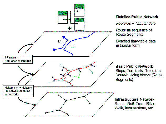
Figure 2 The data model describes several layers of interdependent data
Figure 3 shows a detailed version of the conceptual model.

Figure 3 Conceptual data model for TOP
The next section discusses how the conceptual model was turned into an actual ArcGIS object model.
- Maintaining consistency between a network located on top of another network,
- Features having a network presence on a nearby network and,
- Keeping non-geographic data consistent and updated in conjunction with geographic data.
The key to providing new functionality in an ArcGIS data model is not just designing new structures in the data model schema; new custom object functionality is also necessary if the editing environment has to support these in an easy-to-use and intuitive manner.
In the next section, it will be described how the conceptual model was turned into an actual ArcGIS data model and what key decisions was made regarding the design. The cases where the functionality provided by ArcGIS had to be extended will be examined in detail.
Figure 4 shows an overall view of the TOP object model, combining object inheritance, with relationships between objects (Figure 5 shows an excerpt of the actual data model).

Figure 4 A simplified view of the TOP data model

Figure 5 An excerpt from the actual object model diagram, showing some of the relationships in the object model
In general terms, the custom object functionality implemented in conjunction with the design of the object model provides:
- Assistance while editing the data, in order to keep the multi-layered data consistent and updating the various tables involved
- Custom object Inspectors with extra editing features, and the possibility of modifying the behavior of the custom objects.
- Functionality for checking the validity of the custom objects
A lot of the data objects from the conceptual model could be translated directly into network features, as provided by ArcGIS. This was the case with the elements describing the infrastructure networks and the elements describing Stops and change-possibilities between Stops. These elements are represented in the TOP object model as two separate geometric networks that also contain Connectors that connects the networks to the aggregated description of the area being modeled. Defining these as network features also means that the ArcMap Editor automatically offers the user various kinds of support, when working with the data.
However, the description of the scheduled transportation system (although referred to as the Route Network, it is not a network in the ArcGIS-sense of the word) couldn’t be described using simple geometric networks, and it therefore includes the majority of the designed and implemented custom objects. In most cases, it wasn’t possible to model the real-life objects just using a single object. In these cases, the solution was to use a set of tightly integrated custom objects. The most interesting of these are described in the following sections.
The ability to define attributed RelationshipClasses turned out to be extremely useful, and was used widely in conjunction with some of the advanced custom objects.
More generally, the ArcGIS Geodatabase framework, which provides messaging between related objects, makes it possible to implement functionality that is triggered, when changes happen to related objects. This is essential for providing functionality to update data automatically, and preserve the consistency between data in multiple layers. However, events triggered by changes to related objects are often quite complex to handle, as a change to one object might trigger other changes to related objects, which then in turns triggers new updates.

Figure 6 Turns and related objects
Description
As of yet, ArcGIS 8.1 does not provide functionality for handling turns in network-junctions. In order to store detailed data describing road intersections, the Turn object was added. If necessary a TransportJunction has a set of related Turns.
Each Turn models an allowed turn movement in the TransportJunction, but only in the sense that it stores detail data for intersection delay modeling – it is not part of the logical network. However, when Routes are updated using trace-operations on the underlying infrastructure network, the turns ought to be taken into account (this will be implemented in the near future).A Turn is described using the ID of the related TransportJunction, the ID of the origin-TransportEdge and the ID of the TransportEdge that is the destination. A Turn must be unique.
The implemented custom functionality provides:- Assisted editing – meaning the user can have Turns deleted automatically if the allowed directions of movement is changed on the related TransportEdges. The user can modify this behavior.
A custom Object Inspector implemented for the TransportJunction that makes it easy to create, delete and edit turns related to a TransportJunction.
Custom validation functionality that makes it easy for the user to identify invalid Turns

Figure 7 Stop, StopEdge and StopJunction
Description
Historically, Stops have often been represented in a quite aggregated manner. They have, for instance, been described as being placed in a junction in the infrastructure network. However, if Stops are to be described accurately in a flexible manner, a different approach is needed. As described in the conceptual model, a Stop is a feature with a fixed position, which might have a representation in a nearby network.This is handled in the TOP object model, by adding a couple
of assisting objects: StopEdge and StopJunction. A Stop is
then basically a SimpleJunctionFeature. A representation in the scheduled
transport system, and its position on top of the infrastructure network is then
described by placing a StopJunction on the nearest
point of the TransportEdge on which it has a
representation. A StopEdge is automatically drawn
between the Stop and the StopJunction, but this is mainly to provide visual
feedback to the user. This represents the fact, that the Stop is connected to the TransportEdge.
Custom Functionality
The implemented functionality ensures that if a Stop is moved, the positions of the related StopJunction and StopEdge are updated accordingly. The same thing happens if the relevant TransportEdge is changed or moved. If a TransportEdge is deleted, the connection that is described by the StopJunction and the StopEdge, is also deleted. If a Stop is deleted, the related StopJunction and StopEdge are also deleted.
In more general terms, Stop is a basic building block of the description of a scheduled transportation system – the route network. This means that changes affecting a Stop will often trigger quite a lot of updates to related objects – for instance, if a Stop is deleted all the Routes using it must be updated. Generally the related objects handle all these cases automatically. The user has the option of changing this behavior.
Object Inspectors
An object inspector has been provided, which doesn’t have any editing tools in it, but is mainly used to modify the behavior of the Stop-objects (for instance, setting the maximum search distance within which to find a TransportEdge to connect to).
Validation
A Stop is valid if it is not connected to any TransportEdge, or if it has a single connection. A Stop has a connection if the Stop has a related StopJunction, which is also related to a TransportEdge and a StopEdge. Both StopJunction and StopEdge are invalid if they don’t exist as part of a valid Stop-TransportEdge connection.

Figure 8 RouteSegment runs along (parts of) TransportEdges, between a pair of Stops.
RouteSegments relate to TransportEdges through an attributed RelationshipClass, which works like this: Each instance of the RelationshipClass is a so-called RouteSegmentDetail, which represents the part of a TransportEdge, which lies between two linear references. A RouteSegment is then defined as a sequence of these RouteSegmentDetails. This is illustrated in Figure 9 and the table below.
| RouteSegmentOID | TransportEdgeOID | SequenceIndex | FromMesure | ToMeasure |
| 2 | 3 | 1 | 50 | 0 |
| 2 | 1 | 2 | 100 | 0 |
| 2 | 2 | 3 | 0 | 80 |
Table 1 The Linear Reference based definition of a RouteSegment
A specific RouteSegment is considered valid if the following condition is met: The sequence of RouteSegmentDetails, which make up the RouteSegment, should be continuous. That is to say, the to-point of RouteSegmentDetail n, should be coincident with the from-point of RouteSegmentDetail n+1. This has the implication, that RouteSegments can both cross and overlap themselves without becoming invalid. This very high degree of flexibility is the reason for the design.
While it might seem like easy editing has been sacrificed for flexibility, this is actually not the case. Users need not concern themselves with RouteSegments at all. They are simply maintained on the fly by TOP’s custom objects (primarily Route), when users edit Routes and TransportEdges.
As mentioned while discussing the conceptual model, redundancy is greatly reduced by making sure each RouteSegment is unique, and reusing it for every Route using the same path to connect two Stops. This minimizes redundancy. When a RouteSegment is no longer used by any Routes, it is automatically deleted.

Figure 10 A Route is described as a sequence of RouteSegments
Description
The Route is the central object in the modelling of scheduled transportation. Routes are described as a sequence of RouteSegments, using an attributed RelationshipClass, which only contains a sequence index. The sequence of RouteSegments can be translated into a sequence of Stops and a geographic description completely determined by the underlying TransportEdges followed. As mentioned above, RouteSegments are unique, reused and deleted when not in use.
The Route has a GIS-representation as a polyline feature. This makes it possible for the user to work with the Route as a geographic object, drawing and reshaping it in an intuitive manner. Meanwhile, the table-based data are updated in the background by the implemented custom functionality. For instance, when the shape of a Route is changed, the sequence of RouteSegments describing the Route has to be changed too, and new RouteSegments might have to be created and inserted.
The Route object also contains a great deal of custom functionality that handles the events fired by changes made to related objects with the aim of automatically keeping data consistent when possible. An example could be the reshaping of a TransportEdge, which in turn triggers the repositioning of a set of StopJunctions placed on TransportEdge. This in turn triggers updates to Routes and RouteSegments affected by these changes.
Custom Functionality
- Provides the user with a graphical and intuitive editing functionality, and updates all the relevant data in the background.
- Reacts to changes in underlying data, attempts to keep data consistent when possible.
- Handles input from the user in an intelligent manner, for instance interpreting a loose sketch into a valid Route on top of the infrastructure network.
Object Inspector
The ObjectInspector implemented for Route makes it possible for the user to modify the behavior of the Route object. For instance, if an underlying TransportEdge in the infrastructure network is deleted, should the affected Routes automatically retrace their paths, or should they be left invalid, for the user to update manually.
The ObjectInspector also contains a tabular view of the route, for easy editing of the timetable data.
Validation
A Route is valid, if it consists of a continuous sequence of valid RouteSegments.
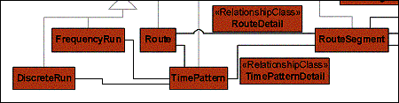
Figure 11 Describing the timetable data in a flexible and compact manner
Description
A TimePattern represents stop-to-stop driving times and in-stop waiting times for a Route. This is accomplished by having an attributed RelationshipClass (TimePatternDetail), which relates TimePattern to RouteSegment. Each of these TimePatternDetails store these data:
| TimePatternOID | Foreign key - refers to the owning TimePattern |
| RouteSegmentOID | Foreign key - refers to a specific RouteSegment. Its position in the Route-sequence is determined by the RouteDetail RelationshipClass |
| Departure | The time of departure - relative to the starting time - from the StopJunc-tion at the beginning of the related RouteSegment |
| Arrival | The time of arrival - relative to the starting time - to the StopJunction at the end of the related RouteSegment |
| AllowEmbarkment AllowDisembarkment |
The possibility for allowing and disallowing embarkment and disembarkment, provides the possibility for establishing points where Routes have to pass at specific times, with allowing passengers to get on or off |
A TimePattern can also be related to a number of DiscreteRuns and FrequencyRuns. They represent one departure for a specific TimePattern, An example of a typical use of TOP's route- and timetable-related classes could be: A public transportation service could be modeled as a RouteGroup. This could then be related to a number of Routes, each of which represents a specific path through the underlying infrastructure network. These variations could be caused by differences in demand over the day or by one-way streets or turn restrictions. Another cause for multiple Routes could be different stopping patterns.
Each Route could have a number of related TimePatterns. This could be caused by varying congestion in the infrastructure network at different times of day.
Finally, Each TimePattern will usually have a number of Runs associated with it, describing the actual departures of the TimePattern.
Custom Functionality
The custom code associated with the TimePattern class provides the following functionality:
- A TimePatternDetail relationship will automatically be created for each RouteSegment in a Route, when a relationship between a Route and a TimePattern is created.
- Driving- and stopping-times can be automatically assigned to RouteSegmentDetails, if the user so desires. The user can modify this behavior.
- TimePatterns will be automatically adjusted when Stops are inserted in or removed from a Route.
- Other situations, where edits performed on – for instance – Routes or TransportEdges, which require updates to TimePattern-data, will also be handled automatically
Object Inspector
The TimePattern class provides an ObjectInspector, which allows easy viewing and editing of driving and stopping times.
Validation
A TimePattern is valid if it moves “forward” in time.
The following shows some screenshots to illustrate the easy and intuitive management of route and timetable based transportation data in TOP. The examples show the process of creating a small prototype infrastructure network, and on top of that editing bus stops and bus routes. When building a simple infrastructure network, ArcGIS standard network technology is utilized e.g. in validating connectivity rules between the subtypes. (See Figure 12)
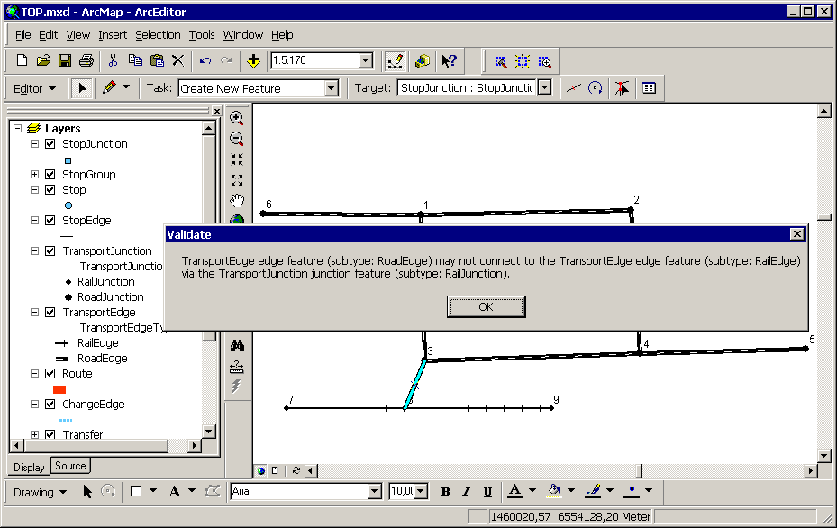
Figure 12 Validating connectivity rules in ArcMap
Creating a new Stop close enough to the infrastructure network will connect the Stop to the network (Figure 13).

Figure 13 Placing a Stop near a Road connects the Stop to the road

Figure 14 Inspecting properties for Stop
Inspecting the properties for the Stop (Figure 14) shows how TOP has extended the ObjectInspector to have several pages in a tabbed dialog. The first page displays the standard ObjectInspector. The next page is a policy inspector; it controls how the objects react to certain events. For Stop there is a policy for whether a Stop should connect to the network (“AutoConnectToTransportEdge”).

Figure15 Policies for Stop
The consequence of setting that policy to “false” and placing a new Stop near the first Stop, is that the new Stop will not connect to the network. (Figure 15 and Figure 16)

Figure 16 The stop does not connect to the network
Routes – which follow the infrastructure network – begin, make intermediate stops and end at StopJunctions, which are the points where Stops are connected to the network. By using the snapping environment in ArcGIS to snap to StopJunctions, it is very easy to draw a Route: Just snap to the StopJunctions, where the Route starts, stops and ends. To make the Route follow a specific path, click near an edge it must use. (Figure 17)

Figure 17 Sketching a Route
The Route will redraw itself to follow the edges. (Figure 18)

Figure18 The Route snaps to the
infrastructure network
The custom ObjectInspector has a special page for showing the stopping pattern for a Route. It shows which StopJunctions the Route stops at or passes without stopping. (Figure 19) It is also possible to change this stopping pattern by clicking in the ‘Stops’ column.

Figure 19 The stopping pattern for a Route
Editing the infrastructure network does not influence the Stops; only the Stop’s connection to the network is changed. The Routes of course follow the new network. (Figure 20 and Figure 21)

Figure 20 Modifying the underlying network

Figure 21 The Route follows the new shape of the network
It is also possible to edit the Route. This will not change the underlying network,(Figure 22 and Figure 23), but it might change the TimePattern if distances between Stops have changed.

Figure 22 A Route can be reshaped

Figure 23 After the Route is reshaped
This chapter describes the excellent opportunities provided by TOP for developing applications, which deal with complex transportation data.
A key advantage to TOP is the rich and productive environment, which is provided for the development of applications on top of the platform. The application development environment consists of:
- The COM framework, which enables the use of several off-the-shelf software development tools
- The ArcObjects API, a very fine-grained set of COM objects and interfaces, which allows very extensive customization of and development with ArcGIS
- The TOP API: Detailed COM interfaces for developing software for working with the transportation data model defined for TOP
- The TOP data model, which is the database schema used by TOP. The data model is very flexible: Users can choose to use only parts of it, and can extend it with new classes and fields as they please
These points show that TOP offers a platform for the development of transportation applications, which surpasses any competing systems in productivity and richness.
TOP focuses on complete transportation systems. This is a distinct advantage, since users will find it easy to adapt TOP to their specific data modeling needs: It is easy to not use a number of the built-in classes in TOP, if a user only needs to work with e.g. car traffic. Working with a complete transportation system in a package, which is only designed for e.g. rail-transport is NOT. Another aspect of this issue is, that having a practical, workable tool for dealing with complete transportation systems allows users to much more easily reap the benefits of the synergetic effect, which can be obtained when one models complete transportation systems on one platform.
TOP also makes it much easier to benefit synergetically from integrating transportation data with various other types of data. This stems from the fact that ArcGIS excels at integrating almost any type of geographic and relational data.
Sections 6.1, 6.2 and 6.3 present Tool/Applications, which are currently under development. These are mainly focused on transportation modeling, since this has been the area, which has first shown interest in TOP.
One of the recently developed tools can be used to extract selected timetable data from the compact data format of TOP (see Figure 24) and display these for closer inspection. The data can be displayed in simple HTML-tables or they can be graphically displayed in 3D (see Figure 25).

Figure 24 A couple of bus routes from the Copenhagen-Ringsted model that has been selected for visualization

Figure 25 A 3D presentation of the two routes from Figure 24 where the x,y-plane is used to describe the geometry of the two routes, and Z-axis is used to display the time dimension
This ability makes it possible to create an easy overview of complex timetable data from multiple routes.
Besides being a useful tool for quality assurance, it also demonstrates two points:
- The high level of detail handled by the TOP model, as shown in Figure 24
- The usefulness of ArcGIS as a platform for development – an amazing amount of existing functionality can be tapped with only modest effort
Assignment models are tools that models real-world flows of traffic using a model of the relevant transportation networks combined with data describing the origins and destinations of traffic flows, often in an aggregated manner.
Assignment models are useful for a wide range of transportation planning issues. For instance:
- Examining the impact of changes in the transportation infrastructure or changes in the timetables for public routes
Providing detailed input for use in environmental impact models and accident analysis
- Examining prognosis scenarios
Assignment models can be useful for examining both local effects (tactical modeling, for instance turning a signalized intersection into a roundabout) and for overall analysis (what is the effect of building a commuter railway line in a city area).
The basic building block of an assignment model is the ability to calculate shortest paths in a transportation system, influenced by various weights. This functionality is in itself very useful, and is available in TOP for both the road network and for the scheduled transportation networks.
A shortest path solver for schedule based networks solves problems like “How to get to B as soon as possible from A, when starting at a specific time, by using public transportation”. This solver will be an extremely useful building block for various more focused tools and applications.
Currently, assignment models for both car traffic and for traffic using public transportation are being developed, which will be available this fall. These models will be updated regularly with the aim of providing state-of-the-art modeling technology in a highly customizable and easy-to-use package for TOP-users.
Key features of the models will be:
- Stochastic User Equilibrium – using capacity constraints in combination with stochastic variables as route choice parameters.
A high level of detail, utilizing the possibility of using the detailed data, which can be stored in the TOP object model.
- The possibility of extracting detailed analysis data concerning traffic flows, for instance showing only the traffic passing a certain road or bridge, all used routes between two traffic analysis zones or the exact changing pattern between routes within a terminal (see Figure 26)
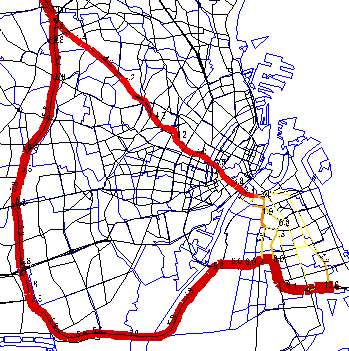
Figure 26 Detailed analysis of traffic flows
Various parts of an assignment model can be very useful in a number of other tools. One of these could be an accessibility analysis tool. Figure 27 shows a result of an accessibility analysis. The varying colors show the time it takes to get from the central station in Copenhagen to each of the Traffic Analysis Zones in the greater Copenhagen area.

Figure 27 Result of an earlier accessibility
analysis
There are several reasons for building tools for accessibility and other analyses on TOP:
- All the data necessary for such analyses is stored in the same open relational database.
- TOP handles both individual and public transportation, and interchanges between modes.
- ArcGIS is an ideal environment for visualizing the results.
TOP includes a whole family of tools, which uses a lot of common calculation modules. Because of that, a great deal of quality assurance and optimizing is ensured.
The Transportation Object Platform, which was presented in this paper, offers a solution for handling complex transportation networks, which is greatly superior to what is available today.
TOP consists mainly of:- An intelligent object model for a complete transportation system, consisting of a data model and a suite of software components, whose main purpose is to facilitate a productive and intuitive editing environment. These components are mainly ArcGIS Geodatabase custom objects and class extensions.
- A number of applications and tools, which perform focused tasks like analysis, modeling and presentation. Some of these tools are stand-alone applications and some of them are ArcMap tools.
A significant strength of TOP’s is, that its data model is comprehensive (its scope is an entire transportation system) and flexible (users can elect to only utilize parts of it and can easily extend it as they see fit).
Another benefit from TOP’s inherent flexibility is that great potential exists for significant extensions to TOP’s basic object model. Currently, two such extensions are in the early planning and design phase. One is an extension, which will model detailed railway infrastructure. This will probably add a number of classes like switch, track and block to the object model. The second project deals with multi-modal logistics, and will:
- Broaden TOP’s support for modes
- Support complex demand data like traveling salesman situations
-Introduce tools for optimizing logistics in a transportation system which includes scheduled transportation
Besides easing the evolution of TOP as a system over time, the inherent flexibility has an added benefit for users (especially for early adopters): The direction of TOP’s evolution will be greatly influenced by user feedback.
Apart from being a system which is ready for use, TOP is also a platform for application development, and excels as such for a number of reasons:
- Developers can use their favorite COM-based development environment with TOP.
- Both ArcGIS and TOP itself offer very rich and fine-grained APIs.
- The inherent openness of TOP and ArcGIS facilitates easy integration with other systems and platforms.
- The fundamental architecture of ArcGIS makes TOP highly extensible, which means that areas in which TOP may be lacking for a specific application purpose, present a development opportunity – not an insurmountable obstruction.
TOP has great potential for easing and supporting the tasks performed by public transport companies, operators of public transport, freight companies, infrastructure owners, planning authorities, and other organizations, which work with infrastructure and transport data.
Finally it is worth mentioning, that TOP has been chosen as the platform for several Danish research projects in which it will form the data handling foundation for modeling transportation of both passengers and freight. Besides demonstrating practical use of TOP, this also means that the applications developed in these research programs will be available for use with TOP in the future.
The authors would like to thank Daniel Holmboe Bang for his help in producing an HTML-version of this paper.
Otto Anker Nielsen (Professor, Ph.D.) oan@ctt.dtu.dk
Center for Traffic and Transport (CTT)
Technical University of
Denmark (DTU)
Building 115
DK-2800 Lyngby, Denmark
Phone: +45 45 25 15
14; Fax: +45 45 93 64 12
Bjarke Brun (M.Sc.) Bjarke.Brun@wsatkins.com
Rasmus Dyhr Frederiksen (M.Sc.) Rasmus.Dyhr.Frederiksen@wsatkins.com
Bo Grevy (M.Sc.) Bo.Grevy@wsatkins.com
Thomas Israelsen (M.Sc.) Thomas.Israelsen@wsatkins.com
Martin Mřller Poulsen (M.Sc.) Martin.Moller.Poulsen@wsatkins.com
Jakob Skriver (M.Sc.) Jakob.Skriver@wsatkins.com
Atkins Denmark
Pilestraede 58
DK-1112 Copenhagen K, Denmark
Phone: + 45 82 34 52 61;
Fax: + 45 33 93 64 30