Abstract
The Hydrograph Analyst (HA) is an ArcView GIS 3.2 extension developed to assist hydrologists in analyzing water levels from wells. The extension enhances ArcView with increased relational database (RDB) capabilities and inclusion of a Hydrograph Document Graphical User-Interface (DocGUI) based upon the Chart DocGUI. The RDB enhancements enable the user to utilize an identify tool, in the View DocGUI, to dynamically retrieve hydrologic information about a well from various tables in an RDB. The Hydrograph DocGUI enables the user to attribute individual water levels on a hydrograph with the attributes dynamically communicated to the RDB.
Water Level Analysis Background
Groundwater flow systems are often very complex and many different parameters affect their responses. Groundwater flow system responses are reflected in water levels measured at wells within the flow system. Hydrologists must interpret some of the complexity by analyzing water levels in a spatial sense over the flow system and temporally during the period of record. The characterization of the flow system is the equivalent of recording a story of major events throughout time and space that have affected the flow system.
The HA was developed to assist hydrologists in analyzing water levels measured at a well. Water level analysis requires the integration of spatial, point, and temporal data. The HA establishes an analysis environment that integrates these three data types. Hydrologists require a point-and-click environment to understand the complex inter-relationships of the physical system affecting water levels at a well. The HA extends the base functionality of ArcView to provide this type of environment for analyzing water levels. This functionality provides the user with the ability to obtain information about the well and surrounding wells by clicking them on a view. The HA also enables the user to generate a hydrograph for a well or a number of selected wells in a view.
A spatial understanding of information affecting water levels at a well is important for interpreting a hydrograph. Spatial data such as the (1) Digital Elevation Model, (2) Land Use and Land Cover, (3) Political Land Survey System, (4) Geologic Faults, (5) Fissures, (6) Land Ownership, (7) LANDSAT images, (8) Geologic Units, and (9) Soils covering a study area can be used to infer trends exhibited by the hydrograph. Typically this data is organized in a GIS database. ArcView provides the base functionality necessary to view and query this data.
Well information and water levels are typically organized in a relational database such as Microsoft Access. One or more tables in the database will store this information. For example, the U.S. Geological Survey's Ground Water Site Inventory (GWSI) system contains 26 tables relevant to analyzing water levels.
Water-level analysis is a process of documenting the hydrologist's understanding of what the data means. The resulting interpretations are usually used to determine the appropriate use of the data. Some data may not be representative of the groundwater flow system. Some data may be representative of a certain time period.
An understanding of the system affecting the water levels enables the user to analyze the water levels displayed on a hydrograph. The analysis process involves the attributing of individual water levels on a hydrograph. The qualitative interpretation is documented with the attribute and the meaning of the attribute is thoroughly described for reference and verification by other professionals.
Water levels are analyzed to achieve many different results. The list of attributes assigned to water levels will vary with the project, hydrologist, and purpose. A hydrologist may support attribute assignment with certain hydrologic conditions and analytical methods. The justification for the flag is usually documented. For example, a precipitation event could be linked to an increase in water levels at a well. The previous example correlates a hydrologic condition (precipitation recharge) to increased water levels. An analytical method could also be used to support the assignment of a particular flag. For example, a statistical analysis of water levels at a well could conclude that a certain trend exists and may be correlated to certain events.
Information and Analysis Environment
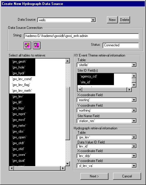
The HA requires information about the organization of the database storing the well information and water levels. This information is specified in the Hydrograph Data Source dialog (Figure 1). The HA expects the user to identify an Open Database Connectivity (ODBC) Data Source which provides a standard mechanism for reading and writing data to and from a database. The Hydrograph Analyst connects to the database via the ODBC Data Source and retrieves information using Structured Query Language (SQL). The dialog box displays a list of tables within the database and the user is responsible for selecting those that contain well information and water levels for each well retrieved from the database. To dynamically retrieve and display wells spatially, the user identifies a table (a site table) storing site information. The site information required by the HA is the site id (a unique identifier for the well), x-coordinate, y-coordinate, and site name. The fields storing the site information required by the HA are identified on the Hydrograph Data Source dialog using the appropriate combo box. Data contained in the site id field of the site table enables the HA to retrieve related data from other tables in the database. Each table containing well information and water levels identified on the Hydrograph Data Source dialog must contain a site id field. The user also identifies the water level table on the Hydrograph Data Source dialog. Once the water level table is identified, the user identifies the site id, water level id, water level date, and water level fields with designated combo boxes on the dialog. The site id field enables the HA to relate the site information in the site table to the water levels in the water level table. The water level id uniquely identifies each water level and the HA uses this information to establish the analysis environment. The HA uses data in the water level date field as x-values and data in the water level field as y-values to create a hydrograph for a well. Both the water level date and water level fields must be real number data type fields. One possible data format for the water level date field is the date in decimal year format (i.e. 1999.55). The Define Relationship to Site Table dialog (Figure 2) asks the user to specify the relationships between the site information in the site table and the related well information and water levels in the water level table.

Figure 1. Hydrograph Data Source dialog
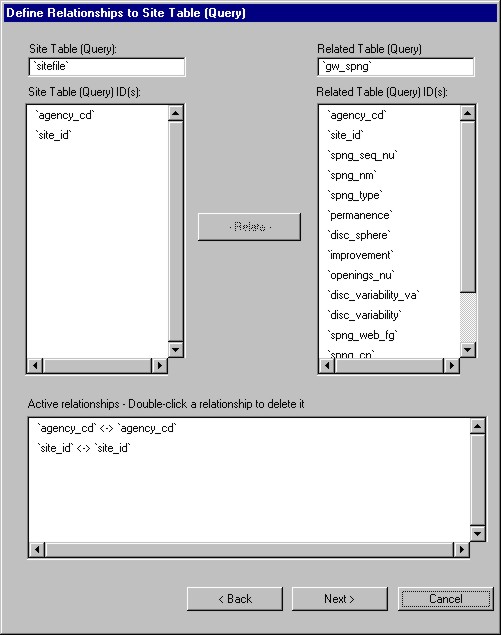
Figure 2. Define Relationship to Site Table
The HA imposes a predefined system for documenting the results of the analysis process. Certain attributes are associated with each water level and assigned by the user. These attributes include a flag, hydrologic condition, and analytical method. An analyzed water level is assigned a flag that documents the results of the analysis process. Each water level has one and only one associated flag. A water level without a flag indicates that the water level was not analyzed. Each flag has one or more hydrologic conditions that support the flag assignment. For example, water levels affected by a significant precipitation event would be assigned an appropriate flag and perhaps a supporting hydrologic condition of 'Precipitation Response'. The HA provides the user with the ability to further qualify the flag attribute with the analysis method contributing to the flag. Each flag has one or more analysis methods supporting the flag assignment. The analysis method is typically the methodology used in analyzing the water level and others used in determining the flag.
A relational database schema (Figure 3) was developed for storage and retrieval of attributes associated with each water level. Each flag is stored and retrieved from a flag table. A flag is related to a water level via the water level id field contained in the water level table and the flag table. Also, the flag table contains fields that: (1) uniquely identifies each flag (flag id field), (2) document the individual who assigned the flag (user name field), and (3) store the date and time that the flag was assigned (flag date/time). The hydrologic condition table stores each hydrologic condition. One or more hydrologic conditions may be related to a flag attribute via the flag id field contained in the flag table and the hydrologic condition table. Other fields in the hydrologic condition table (1) uniquely identify each hydrologic condition (hydrologic condition id field), (2) store the date and time that the hydrologic condition was assigned (hydrologic condition date/time field), (3) record the individual who assigned the hydrologic condition (user name field), and (4) contain the hydrologic condition (hydrologic condition field). The analytical method table stores each analytical method. One or more analytical method may be related to a flag attribute via the flag id field contained in the flag table and the analytical method table. Similar to the hydrologic condition table the analytical method table has fields that (1) uniquely identify each analytical method (analytical method id field), (2) store the date and time that the analytical method was assigned (date/time field), (3) record the individual who assigned the analytical method (user name field), and (4) contain the analytical method (analytical method field).
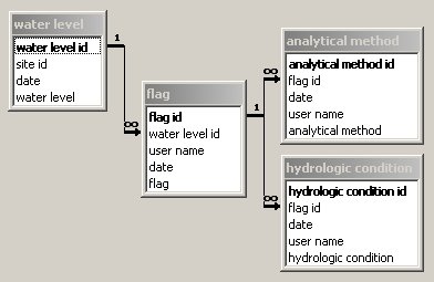
Figure 3. Database schema
The user has the option to specify the attributes used to analyze water levels. The Define attributes for data flagging dialog provides the user with the ability to specify flags (Figure 4), analytical methods (Figure 5), and hydrologic conditions (Figure 6) that are specific to the particular application of the HA to analyze water levels. Each attribute has associated definitions that are stored with the ArcView project. The HA initially utilizes default attributes and attribute definitions for flags, analytical methods, and hydrologic conditions.
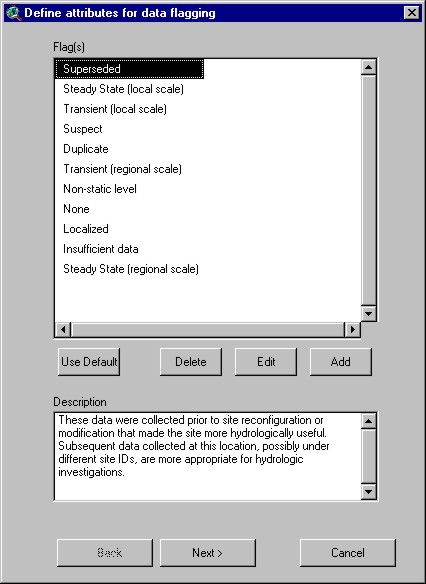
Figure 4. Define attributes for data flagging - flags
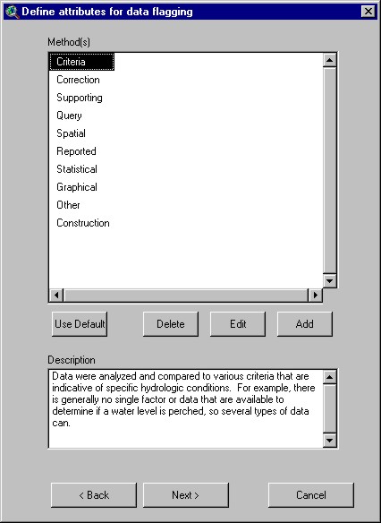
Figure 5. Define attributes for data flagging - analytical methods
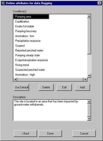
Figure 6. Define attributes for data flagging - hydrologic conditions
Water Level Analysis
A map view of spatial data is easily integrated with sites from the Hydrograph Data Source. Within a View, the user may add a site theme by clicking the Add Site Theme menu item on the Hydrograph menu. The Add XY Event Theme from Hydrograph Data Source dialog (Figure 7) appears and prompts the user to specify a Structured Query Language (SQL) 'WHERE' clause. Site are selected that satisfy the criteria specified in the 'WHERE' clause.
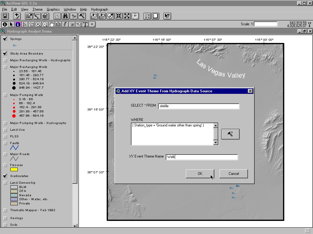
Figure 7. Add XY Event Theme from Hydrograph Data Source dialog
The addition of an XY Event Theme to a view enables the user to utilize the Identify Hydrologic Information tool. The Identify Hydrologic Information tool (Figure 8) lets the user display hydrologic information about sites on a view by clicking on them with the mouse. This tool functions similarly to the Identify tool but has additional functionality. In addition to displaying attributes of the features clicked on a view, the Identify Hydrologic Information tool displays records (Figure 9) from various tables in the Hydrograph Data Source that are related to the site. If the Hydrograph Data Source is connected to the GWSI database, 26 separate tables will be queried by the HA to retrieve data that is related to the site clicked on the view.
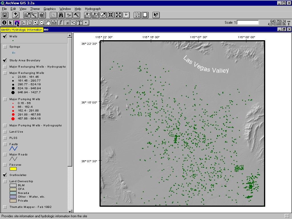
Figure 8. Identify Hydrologic Information tool

Figure 9. Identify Hydrologic Information results
A hydrograph or multiple hydrographs may be generated from an XY Event Theme derived from the Hydrograph Data Source. The user activates an XY Event Theme of sites and selects one or more sites on a view by using the Select Feature tool. When the user clicks the Create Hydrograph button (Figure 10), hydrographs are generated for each selected site that has appropriate data.
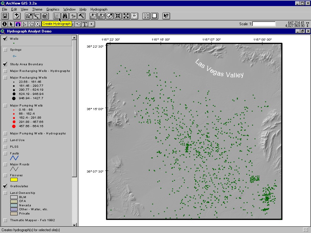
Figure 10. Create Hydrograph button
Hydrographs generated by the HA are accessible by clicking the Hydrograph icon in the project window. The Hydrograph document graphical user interface (DocGUI) contains a collection of controls that are used to interact with the Hydrograph and analyze data. The DocGUI is comprised of a menu bar, a button bar, a tool bar and a set of popup menus. Many features in the Hydrograph DocGUI are similar to those in the Chart DocGUI. Only those Hydrograph DocGUI features that are not included in the Chart DocGUI will be specifically discussed. The Hydrograph DocGUI (Figure 11) provides various buttons and tools for selecting data on the hydrograph. The user may open the hydrograph's table by clicking the Open Hydrograph Table button (Figure 12). The default Table DocGUI provides various tools, menus, and buttons to interact with the data. A desired selection for the hydrograph may be obtained by clicking the (1) Select All button, (2) Select None button, (3) Switch Selection button, or (4) Query Builder button on the Hydrograph DocGUI. The active selection on the hydrograph may be altered with the (1) Erase tool, (2) Erase with Polygon tool, and (3) Select with Polygon tool. Both the Erase tool and Erase with Polygon tool are familiar to Chart DocGUI users. The Select with Polygon tool allows the user to select a point or a group of points by drawing a polygon around the area of interest (Figure 13). Only active and selected data points are actually displayed on the hydrograph.
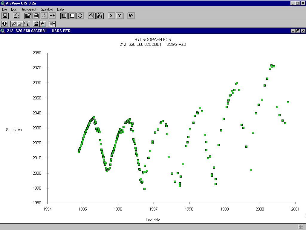
Figure 11. Hydrograph DocGUI
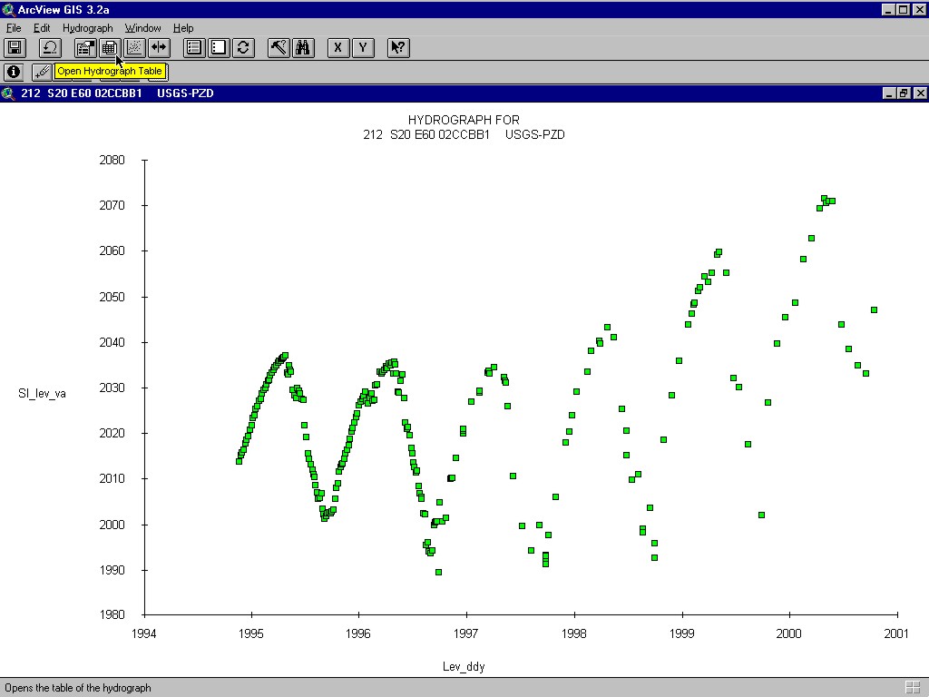
Figure 12. Open Hydrograph Table button
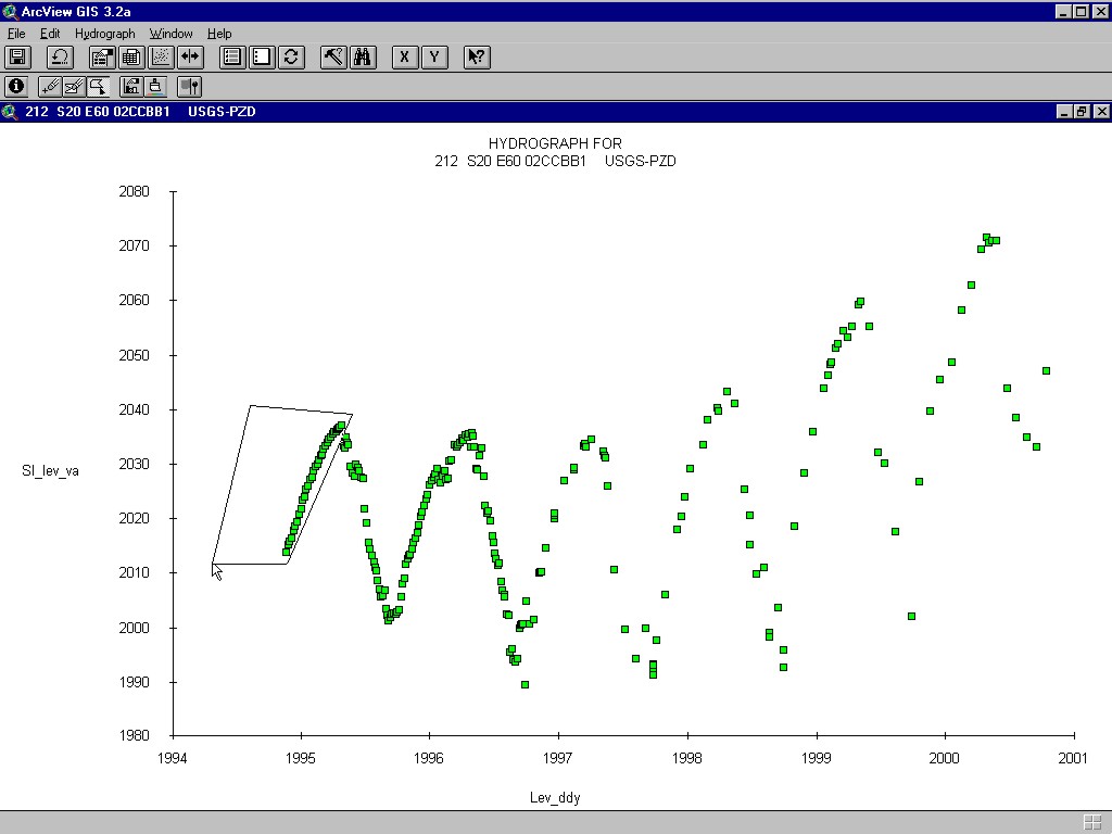
Figure 13. Select by Polygon tool
The data points displayed on the hydrograph may be analyzed point-by-point or as a group. Analysis is performed using the Flag Point(s) tool. A mouse click on a point of a Hydrograph document will activate the Flag Data Dialog for analysis. A mouse click on the Flag Point(s) tool also activates the Flag Data Dialog (Figure 14) for analyzing a group of points displayed on the hydrograph. Whether selected point-by-point or as a group, a water level is assigned a flag, one or more hydrologic conditions, and one or more analytical methods that support the assignment (Figure 15).
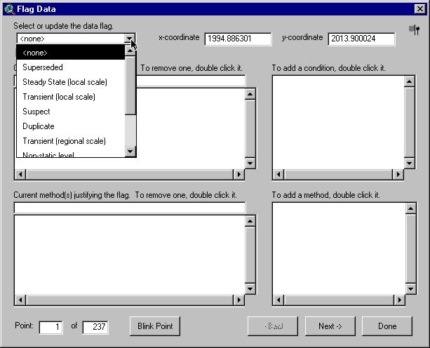
Figure 14. Flag Data Dialog

Figure 15. Completed Flag Data dialog
Conclusion
The HA was developed to assist hydrologists in analyzing water levels at a well. The HA establishes a point-and-click environment that integrates point, spatial, and temporal data that the hydrologist uses to analyze water levels. Hydrograph generation is simple with the HA. The Hydrograph DocGUI provides features to qualitatively analyze water levels. The results of the analysis are dynamically recorded in a relational database and linked to each water level analyzed.