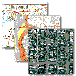
The United States Forest Service has a need for aerial sketchmapping to map forest pest infestations and wildfire extents from the air. Traditionally, this has been done with paper maps, hand-sketched polygons, and digitizing into Arc/Info and ArcView. A system has been developed by adaptation of the GeoLink software, GPS, mobile pen-computers, and flat-panel displays to provide a robust aerial mapping system. Key concepts include arc, point, multi-point, and polygon sketching; navigation against digital USGS DOQ and topographic imagery; and immediate translation of data into ArcView- and Arc/Info- compatible coverageĺs for fast importation into GIS.
Michael Baker Jr., Inc. (Baker) was contacted in 1997 by the USDA Forest Serviceĺs Remote Sensing Applications Center (RSAC), located in Salt Lake City, UT, to participate in an evaluation process of GPS enabled field data collection software for potential use in their aerial sketchmapping program. Bakerĺs patented GeoLink Mapping System software was evaluated along with a number of software mapping products for consideration as the mapping and system integration software, to be used in a conceptualized aerial sketchmapping system. As the result of the evaluation, and staff meetings between RSAC and Baker, GeoLink was selected as the software to be used in the proposed system. Reasons for the selection of GeoLink included the patented data attribution, display capabilities, sketching capabilities, and the willingness by Baker to undertake customizations on the GeoLink software. GeoLink was also a primary candidate due to GeoLinkĺs ability to output raw GPS data into file types utilized by Esri software. GeoLink would allow more flexibility for use with Esri software; utilizing internal programming that allows GPS files to be translated into three Esri formats, Arc/Info PC, Arc/Info Workstation, and ArcView shapefiles. Once GeoLink was selected, a process of core software modifications was begun to craft GeoLink into a robust, capable aerial sketchmapping system. At this time three separate phases of software modifications, system implementation (during field season), and further modifications (suggested by field users), have been accomplished.
The USDA Forest Service agency responsible for funding and administering the development of the aerial sketchmapping project is the Forest Health Protection and Forest Health Technology Enterprise Team, located in Fort Collins, CO via the RSAC in Salt Lake City, UT. The project manager in charge of this Forest Service effort is Dr. H. Ross Pywell, GIS and Spatial Analysis Program Manager, in Fort Collins, CO.
The USDA Forest Service has performed aerial sketchmapping for forest health since the 1940ĺs. The overall reason for the program is to measure forest health by a relatively rigorous inventory of pest infestations. Historically the inventory has been accomplished by sending an aerial observer aloft in an aerial platform, (typically a high performance monoplane, such as a Cessna 206), equipped with paper topographical maps, and a writing device. Flights typically range between 1,000 and 3,000 feet above the ground. The aerial observer would view the ground, referencing himself/herself on the hardcopy topographic maps, or aerial photography, by the topology seen below, while scanning the region for areas damaged by insects, disease, or weather events. Once damaged areas were encountered along flight transects; the aerial observer would draw lines, points, or polygons on the paper maps. An abbreviated set of numbers were developed to annotate the individual features, which in the case of pest infestation, would log the species of tree, type of pest, and an estimate of area or number of infested trees.
When the flight was completed, the aerial observer would hand off the maps/photos to the Geographical Information System (GIS) department, for a digitizing and data entry process to enter the collected data into the GIS database. Each mapping session could yield up to several hundred small polygons, with associated data annotations, requiring an extensive effort to correctly enter the data into the GIS database.
The primary GIS platform for the USDA Forest Service is Esriĺs Arc/Info, however, initial data editing can be completed by the sketchmapper directly following the flight mission using ArcView, also produced by Esri. The USDA Forest Service has developed a full range of utilities that create additional functions in ArcView to process digital sketchmapping data.
The recent advancements in portability, microprocessor speeds, computer system performance, computer display devices, and increasingly efficient uses of GPS and GIS technologies have led the USDA Forest Service to conceptualize and develop a digital data collection system, with the aim of increasing both data collection and data management efficiency. The proposed system is to be portable, and composed of a fast computer, remotely located flat panel display, stylus/pen data entry, digital topographic map imagery, and sub-decameter accurate GPS receiver. The new system is to enable the aerial observer to collect data using a digital topographic image, as a background coverage, draw the pest infestation polygons directly onto the flat panel display, and quickly enter the required annotations for the GIS database.
The aim of the system is to accommodate the needs of the airborne aerial observer during the data collection session, and provide a system, which will deliver a digital shapefile and associated database, to the GIS staff. The biggest advantage is that aerial observer can spend more time identifying damaged areas, than attempting to track positions on maps. System functional gains include an increase in the speed of data collection and a reduction in the time expended editing data during input to the main GIS database.
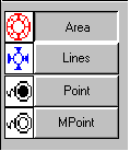
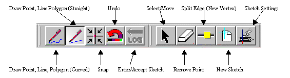
The GeoLink Sketchmapper system consists of the core GeoLink mapping module, and two additional modules (Sketching and Raster). The patented core GeoLink Mapping System allows for the rapid mapping and attribution of features, which consist of lines; offset lines; points; offset points; averaged points; and averaged offset points. With the addition of the Sketching Module, users enable functions to collect additional features which include, sketch lines (both straight and curved), sketch points, sketch multi-points, and sketch polygons (both angled and curved). Sketch Multi-Points allow the user to multiple points, that share the same attribution, at one time, adding another valuable timesaving function. Although the Sketching Module is available to be used without additional modules, it has been shown to work best with the use of the Raster Background Map Module.
The Raster Background Map Module is ideal for orientation, updating GIS files, navigation, checking the accuracy of existing paper maps, collection of ground control coordinates, and ground truthing the classification of features seen on an image. The module works with scanned paper maps, USGS Quad Maps, aerial photography, and satellite imagery. The system also allows the user to load multiple maps, both raster and vector, for the most complete background display.
When utilizing GPS and GIS in a project, accuracy is usually one of the first topics that are brought to the discussion table. Several factors must always be weighed to determine the level of accuracy that is needed. Such factors include (but are not limited to) the intended end use of the data, methodology for data collection, type of GPS receiver, Datum and Projection, and skill and availability of staff.
ôManualö sketchmapping (absence of field computers) has inherently more human error involved than the newer digital sketchmapping. The sketchmapper has roughly 15 seconds per square mile, using typical airspeeds of 90-120 knots, to accurately orient himself/herself to the hardcopy map/photo, locate the damaged areas, sketch, and attribute all of the features. The Forest Service sketchmappers use a wide variety of maps. Those in Rocky Mountain States typically use 1:100,000 scale USGS 30x60 minute quadrangles, while others prefer Thematic Mapper Satellite-based imagery. Map size and type must be carefully examined, to find the right combination of the number of maps, versus the visible detail. Obviously, the smaller the map, the more that will be needed to complete the flight mission, which is more maps that the sketchmapper must keep track of in a bouncing, pitching, yawing plane. Fatigue of the sketchmapper must also be considered. The sheer number of maps that must be maintained and tracked compounds the effects of constant ground orientation, sketching, and attributing. Flight missions are expensive, partly due to the rising cost of fuel, which does not allow for the mapper to sit back and relax. On a typical flight mission, which lasted for six hours, one sketchmapper collected and attributed 980 polygons. That breaks down to roughly three areas per minute that must be located, examined, mapped, and annotated for six straight hours.
The accuracy or lack thereof, predominately rests on the shoulders of the sketchmapper. They must be constantly orienting themselves on the hardcopy maps, in relation to the ground. This can be particularly difficult in flat terrain, and days with lower visibility. Using the manual method, it has been shown that features could easily have a placement error of several hundred feet. The errors would be passed right along to the GIS staff, who could potentially compound the error further through digitization.
When the Forest Service was evaluating new systems, another factor was the turn-around period of data. With the manual system, it was not uncommon for several months to pass before updated data could be placed in the hands of the end users. The rapid turn-around of data is particularly crucial for many types of pest infestations. The window for detecting small, bug infestations may only be a couple of weeks (for telltale signs), before the problem could explode into a large-scale assault on the surrounding forest.
Even though the manual system has much inefficiency, it must be said that the system does work.
The digital system of sketchmapping reduces the amount of error that is found with the manual system. The mapper no longer has to struggle to orient himself/herself, through the use of digital raster images, used as background maps, and with the GPS positioning of the aerial platform shown directly on the screen. (Shown Below).
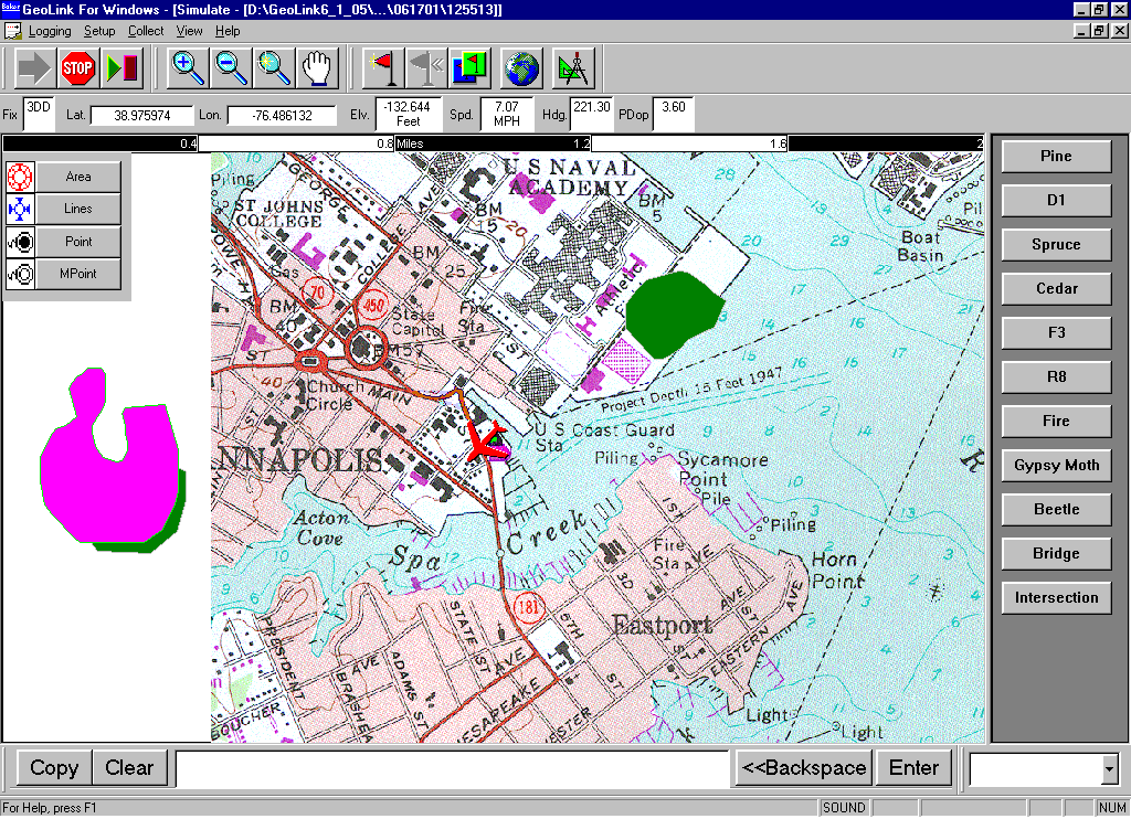
Through testing, the Forest Service has also been able to decrease errors with the use of different types of raster images. During test sessions in the Southern Region (R8), flight missions were conducted throughout the growing season to spot small outbreaks of the southern pine beetle. Points were sketched at known locations, such as intersections and bridges. The points were translated into Esri shapefiles, and placed as background information for ground field crews. The results showed that features could range anywhere from 3-500 feet from the actual location. The Forest Service determined that the error was too high, and searched for a better solution. The answer was found with digital ortho-photo quads (DOQĺs). Since the sketch positions are referenced from viewable features on the background map, the DOQĺs were the logical choice. The DOQĺs meet National Map Accuracy Standards for 7.5-minute quads, which relates to roughly 40 feet of error for point features.
Through Forest Service feedback, the GeoLink Mapping System has gone through several phases of modifications, with future modifications planned, to meet the Forest Serviceĺs current needs, and address potential issues that may arise in the future. Many of the early modifications to the mapping software were due to the type of hardware being utilized by the sketchmappers. Stylus/Pen based computers, were chosen by the Forest Service, due to ease of use for sketching polygons, while flying in a plane. The leading factor to most GeoLink modifications has been the hardware that it available today for the sketchmapping community.
Traditional laptops force the mapper to use the small button mouse, or touch-pad to create the sketch features. Due to constant movement and turbulence in the aircraft, it was determined to be too difficult to control the small cursor controllers. Stylus/Pen remote display panels, with sunlight readable displays (1500 nits), were the logical choice, which created a smooth transition between writing on hardcopy maps, and drawing on a computer screen. However, due to the lack of room in the aircraft, external keyboards would not be effective. The mapper typically has the display screen held on their lap, or mounted directly in front of them. These factors led to modifications in GeoLink, for the creation of a virtual and programmable, keyboard (Below Left) and quick buttons (Below Right).
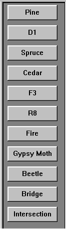
The mapper can configure the quick buttons before flight, and allow the fast (one touch of the pen) attribution of a sketched feature. Several buttons may be selected (one after the other), to annotate the feature with multiple attributes chosen from the virtual keypad. Each selection is shown at the bottom of the display screen (Shown Below). All attributes that are entered, are automatically separated by a comma, saving the mapper valuable time, which allows them to study more features on the ground. The sketchmapper is also able to type directly into the attribution dialog box, (for annotations that are out of the ordinary, or not part of the originally configured virtual keypad), creating added flexibility to the virtual keypad.

One of the largest timesaving modifications to GeoLink, has been the addition of the Splittiff utility. Large raster images can dramatically slow down the screen regeneration time, causing longer flight duration, and subsequently higher expenditures to map terrain. Splittiff, whether used directly in GeoLink, or separately for batch processing outside of GeoLink, reduces the amount of the raster image necessary for screen regeneration. Images are broken down into tiles, and only the tiles that are in, or next to the screen display, are regenerated, dramatically increasing refresh speeds. The utility can be used for files as small as 1 megabyte, which allows the mapper to have multiple raster images loaded into the background map list, without diminishing regeneration speed.
During flight missions, more flexibility was needed for the location of screen regeneration, as well as the need for background map rotation. It is more mentally taxing on the mapper to attempt to orient himself/herself to a background map displayed with North at the top of the display, when the flight path may be headed in another direction. The addition of background map rotation has been added, for easy ground to map orientation. At any point during logging, when the display screen is regenerated, (and the mapper has enabled the setting for map rotation), the last known heading is calculated and used to rotate the background map(s), so that the primary direction heading is oriented to the top of the viewable screen.
Settings have also been added to allow the user to choose the location on the screen to which he/she would prefer their current location to be displayed. The user has nine different options for position placement. In addition to a user-defined regeneration, GeoLink has also been modified for a ôSmartö setting. GeoLink will analyze the general direction of travel, and regenerate the positional marker to the opposite side of the screen. For example, if the flight mission is travelling NW, when the screen regenerates, the airplanes current location will be initially displayed in the SE corner. The software determines, based on the previous trend, that the mission path will continue to follow a similar direction of travel, reducing the number of times the screen is required to regenerate.
Modifications have also been added to the sketching tools available to the mapper. Such tools (Shown Below) allow the snapping of lines to points, setting snapping tolerances, editing vertices (for arcs and polygons), splitting arcs and polygons to create new vertices, ability to delete entire points, arcs, and polygons, or simply delete one node of an arc or polygon.
One such future modification, will be the creation of a utility, which can be accessed from outside GeoLink (similar to Splittiff). The Large Shapefile Optimization Utility is being designed to split up large shapefile coverages, into manageable units catalogued to optimize regeneration and navigation relative to current GPS position. During the tiling process, the X, Y, and Z coordinates will be transformed into a user specified datum and projection to reduce the time required to process each coordinate during screen regeneration. Also, the numerical format of the vertices will be changed to reduce the amount of memory required hold each position while keeping the accuracy level the same. Changing the format of the numbers will reduce the number of disk accesses and the amount of data transferred from the hard drive for screen regeneration. The vision for this utility will be to design it for application to shapefiles which cover a large area in extent or contain a large number of line-work features or point features with associated data. 2D and 3D Polygon, Line Point, and Multi-point shapefiles will be supported.
To counteract the problem of mobile computer system performance degradation, caused by the tracking and display of many sketched features collected during a given logging session, GeoLink will utilize a Proto-Shapefile, which will work in a similar fashion as the Splittiff software. This process will section the logged features, and only regenerate those near, or in the viewable display. This will speed the regeneration of the background map (all done without any user input), and allow the sketchmapper to continue work at normal speed. Regeneration times are expected to be nearly as fast, as if the logging session had just started.
Through the use of the Proto-Shapefiles, sketches will be shared between multiple mappers on the same aerial platform. This particular modification primarily hinges on the workstations containing a local area network (LAN) capability, which will enable surveyors to connect two or more workstations together during flight. This configuration will allow at least one surveyor to be sketching on each side of aircraft, but through the transfer of sketch files, be able to view, on his/her own screen, the features being collected by the other surveyor(s) in near real time.
The USDA Forest Service has expended many man-hours examining different types of hardware available today, as well as the configuration of that hardware, to find the best- suited equipment to meet their sketchmapping needs. Many determining factors for hardware selection arose during evaluation phases. Ideally, there would be one aerial platform, from which sketchmapping is performed. This would eliminate problems of loose cables and cords in the aircraft, and allow the equipment to be wired directly into the planes electrical system, eliminating the need to carry portable power supplies. However, this is the real world, so best fit solutions must be found.
It is uncommon for only one plane to be used, and often the aircraft is privately owned. Because of this, the entire system must be transferable from one vessel to the next, which means that equipment can not be mounted in racks attached to the plane, nor can cables be routed in the fuselage, out of the mapperĺs way, due to time constraints.
Selection of hardware was also determined by, among others, size, weight, processing capabilities, number of peripherals, display quality, and heat distribution. Because of these factors, and the lack of acceptable equipment, the Forest Service has turned to equipment manufacturers to custom build certain pieces of hardware to meet their needs.
The current equipment setup consists of an 850Mhz laptop, with a minimum of 200MB of RAM, remote touchscreen display panel, and a GPS receiver. Power is supplied to the hardware through a specially designed power distribution, which has the ability to draw from the aircraftĺs 12VDC or 28VDC supply.
Through the process of evaluating and testing software and hardware setup and configurations, the Forest Service has gained a great deal of experience, which will be compiled into a ôDigital Aerial SketchMappers Handbook.ö The Forest Service has shown the cost-saving advantages of the digital system, which are estimated to be between $7,000 and $15,000 per Region, per year. They have seen the bulk of the savings have, and will, come from the reduction of man-hours needed to post-process the hand drawn information. Benefits that at this point do not have a measurable monetary value, are the turnaround speeds, from collector, to end-user. The Forest Service should be commended for the dedication, knowledge, and willingness to communicate with manufacturers, as well as end users, to create an aerial mapping system to match their exact needs, yet be flexible enough to be used in other arenas.
H. Ross Pywell, Program Manager GIS & Spatial Analysis USDA Forest Service, FHTET
Charlie Schrader-Patton, Remote Sensing/GIS Analyst RedCastle Resources, Inc.
Schrader-Patton, C. 2001. Digital Aerial Sketchmapping Interim Project Report RSAC-LSP-3400-RPT2
David Stoltenberg, NASA Tech-Link Program Manager Big Sky Economic Development Authority
Steve Bohne, Senior Software Engineer Michael Baker Jr., Inc.