Modeling Signal Carrying Paths
in a Network of Telecommunications Facilities
with ArcGIS 8.1

Martin Brock, Telcordia Technologies

Modeling the signal carrying paths within a telecommunications network poses unique challenges for a GIS based, facilities management system. Telcordia's Network Engineer 2.0 provides a telco FM system within ArcGIS 8.1, using a hybrid of standard ArcGIS network modeling and a custom network model, constructed within the ArcInfo Object Model, suited to managing the many signal carrying units in telco network facilities. The paper addresses merits and limitations of the ArcInfo Network Object Model and discusses Network Engineer's extensions of ArcGIS 8.1. The anticipated reader is an experienced developer of custom ArcGIS applications.

Telcordia's Network Engineer 2.0 employs ArcGIS 8.1 to map the facilities of a telecommunications network and to manage data associated with the facilities. Typical telecommunications facilities include cables, composed of copper pairs or fiber strands, and a variety of equipment operating upon the signals carried by those cables. NE 2.0 models cable and equipment facilities as ArcMap features and employs standard ArcMap methods to manage feature attributes and the geometric relationships between facilities; however, ArcMap's feature level tracing does not easily support relationships between the signal carrying units of telcommunications facilities, pairs, fibers and equipment ports.

Representing connections between signal carrying units with standard ArcMap methods essentially requires modeling individual units as map features; however, the very large number, possibly thousands, of units associated with a single facility makes that modeling problematic. To be highlighted on a map by standard tracing methods, a unit feature must belong to a graphical feature layer, and ArcMap would then be required to draw thousands of coincident linear features. Because connections between units typically occur in ranges, representing units as individual features increases data storage requirements by storing much redundant information, and the representation also adversely affects trace performance, since each unit must be traced independently.

ArcMap's geometric network vs. a network of signal carriers

NE 2.0 represents connections between telecommunications facilities by modeling the facilities as network vertices and modeling connections between units as edges joining the vertices. A range of connected units is an attribute of each edge, so a single edge can represent connections between many signal carriers. Note: we use the terms "vertex" and "edge" in an abstract, graph theoretic sense here. Because ArcMap's model of the geometric relationships between map features shares similar terminology, an NE user must carefully distinguish ArcMap's "geometric network" from the network of signal carriers in Network Engineer.

Although cables are "edge features" and equipment are "junction features" within ArcMap's geometric model, both cables and equipment are "vertices" (synonymous with "junction" or "node"), in the graph theoretic sense, within NE's model of signal carriers. In ArcMap's geometric network, an edge feature joins two junction features geometrically, so for example, a cable might join two equipment, a cable might join an equipment and a splice closure, or it might join two splice closures.

In Network Engineer's network of signal carrying units, an edge (or connection) is a relationship between two cables or between a cable and an equipment or between two equipment (or between a facility and itself). The NE connectivity network is a collection of facilities (cables and equipment), wherein each pair of facilities is related by zero or more connections, each representing a range of connected facility units (pairs, fibers or ports).

Figure 1. A single edge in NE's connectivity model relates the Equipment to Cable 1 and a second edge relates Cable 1 to Cable 2. The first edge represents connections between four consecutive ports on the Equipment and four consecutive pairs in Cable 1. The second edge represents connections between the four pairs in Cable 1 and the four pairs in Cable 2.

Administrative cables

In the telecommunications industry, network engineers commonly designate a sequence of connected units in many network facilities as an administrative unit and designate a collection of adminstrative units as an administrative cable. In Figure 1, four signal carrying paths are divided between two administrative cables, A and B.

The endpoints of an admininistrative cable are distinquishable as source and destination; therefore, an administrative direction characterizes each connection between NE facilities. If units in a particular facility belong to administrative cables, Network Engineer can label the facility to indicate the administrative units to which facility units belong, or equivalently, the administrative source of each unit's signal.

Figure 2. The administrative label beneath Cable 2 indicates that the two pairs in the cable carry the signal from the first and second ports of the Equipment, labeled A1 and A2. The two pairs in Cable 3 carry the signal from the third and fourth ports of the Equipment, labeled B1 and B2.
Figure 3. The units of an administrative cable, or a single administrative unit, can follow divergent paths.
Figure 4. Administrate cable A originates on the first and second ports of the Equipment and terminates on the third and fourth ports.

Tracing

The ability to easily trace the source and/or destination of a signal in a unit of some facility, and to identify other facilities with units carrying the same signal, is critically important in a telecommunications application. Identifying the facilities carrying signals from a significant collection of sources or to a significant collection of destinations, comprising the units of an administrative cable, is also important.

ArcMap's standard network analysis functions trace geometrically connected features, but the standard tracing methods cannot trace signal carrying units. Network Engineer's custom connectivity model permits a user to trace a single administrative unit from any constituent unit to its source or to destinations. A user may also trace an admininistrative cable, or the paths originating at any collection of a facility's units, from the facility to sources or destinations, without tracing each unit separately. The product identifies traced facilities, facility attributes and path attributes like total length and attenuation.


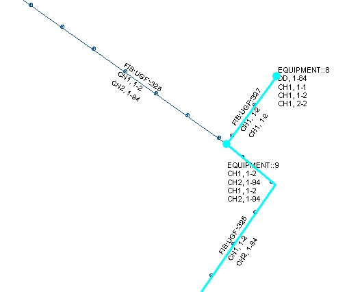
Figure 5. ArcMap displays the result of Network Engineer's signal tracing. Unit 1 in administrative cable CH1 carries a signal from the cable FIB:UGF::325 to the unit's source, the 85th port on EQUIPMENT::8.


Figure 6. Some of the results available from NE's trace reporting tool.

Limitations of ArcInfo's Network Object Model

During the development of Network Engineer 2.0, we explored ArcInfo's Network Object Model, the foundation of ArcMap's geometric network, as a means of representing unit level connections. We employed an instance of the Network Object Model outside of a geometric network with considerable success, but difficulty maintaining the associated database and reconciling conflicting versions of the network eventually led us to develop a custom network representation within ArcInfo's more general Object Model.

Within our custom application of the Network Object Model (NOM), we constructed a network of signal carrying units as described above. We represented a telecommunications facility as a junction in the NOM, associating the Network junction with the map feature representing the facility. We represented a connection between facility units as an edge in the NOM, associating the Network edge with a custom connection Object, within the ArcInfo Object Model. Our Network edge was not associated with an ArcMap feature.

The NOM's standard tracing methods did not effectively support our tracing requirement; however, by representing a range of connected units as a Network weight, associated with the Network edge in our model, we were able to effectively implement a custom signal trace using the NOM's ForwardStar component.

The Network component is a black box component. Constituent tables are not conventional ArcInfo Objects. To optimize spatial database queries, the model stores many discrete junction, edge and weight data in large, binary objects. Examining the data is therefore possible only through the NOM components. Debugging corrupted data was therefore challenging; however, despite that difficulty, the Network Object Model met our initial requirements well.

Unfortunately, our design did not properly anticipate limitations of the Network Object Model. ArcMap does not employ NOM components outside of its geometric network, and the application's standard version reconciliation methods do not reconcile conflicting versions of a NOM instance outside of a geometric network. Reconciling conflicting versions of our Network dataset therefore posed fundamental difficulties, requiring us to seek another representation for NE's network of signal carriers.

Representing connectivity outside of the Network Object Model

Network Engineer 2.0 provides facility level connectivity and tracing through ArcMap's standard Network Analysis interface but represents unit level connectivity with a custom model and custom tracing methods. The custom connectivity model retains some advantages of ArcInfo's Network Object Model but represents network elements as conventional ArcInfo Objects.

Our implemenation performs well and outperforms the NOM on small datasets; however, the NOM's balanced Forward Star representation is designed for very large datasets and suffers performance overhead more notable on smaller datasets. Our model also anticipates the spatial database query problems which inspired the NOM's design. We have not implemented spatial balancing, but the model permits it if necessary, and we expect the performance of our tracing methods to scale well to large datasets.

Map features representing facilities are associated with an ArcInfo Object called a Connectivity_Vertex. A Connectivity_Edge Object relates two Connectivity_Vertex Objects as described above. A range of connected units in each connected facility is an attribute of the edge. Tracing requires only successive queries for Connectivity_Edge Objects using standard methods within the Geodatabase Object Model.

Reconciling administrative label conflicts

Network Engineer 2.0 maintains administrative naming information with standard Geodatabase Objects and stores the label of each facility as an attribute of the associated ArcMap feature. NE's connectivity subsystem automatically updates the labels of affected facilities when a user edits connections or administrative names. That approach permits an NE user to easily exploit ArcMap's simplest, standard label generation methods.

Unfortunately, storing administrative labeling information for each connected facility can create version conflicts which are very difficult and costly to resolve within ArcInfo's versioned database model. A single connection edit can affect administrative labels throughout a network, and multiple connection edits accompanied by administrative name edits can have very complex, very far reaching effects on many different facility labels. Reconciling those conflicts essentially requires NE to ignore version conflicts and reconstruct conflicting labels after reconciling versions. Because that task is programmatically difficult and otherwise problematic within the ArcInfo versioning model, NE 2.0 limits connection editing to avoid administrative labeling conflicts between versions.

To eliminate the limitations imposed on connection editing in parallel versions, NE 2.0.1 adopts a new approach to administrative labeling which employs ArcMap's powerful, advanced label expression interface. The approach still provides an NE user the full complement of ArcMap's standard labeling tools, but it does not require labeling information stored in versioned tables or a label as a feature attribute. Instead, NE 2.0.1 stores admininistrative names only for source facilities and traces to construct a facility label only when a label is needed.


Figure 7. Network Engineer 2.0.1 employs ArcMap's advanced labeling method to construct administrative labels on demand, eliminating the difficult task of reconciling conflicting versions of the labels.

The AdminLabel method available in NE 2.0.1 provides access to the product's custom signal tracing through ArcMap's powerful, advanced label expression interface. The label generation method intelligently avoids redundant tracing to construct administrative labels very rapidly as ArcMap refreshes the feature labels on its display. Because tracing to determine administrative labels eliminates the need to reconcile conflicting versions of the labels, NE 2.0.1 permits users working in parallel greater flexibility in editing connections.

Lessons learned

ArcGIS 8.1 is a remarkably powerful, highly extensible system for developing facilities management solutions integrated with Esri's GIS. A system of its scope and complexity inevitably poses tremendous challenges for a system integrator, but ArcGIS offers a rapidly maturing platform for FM software development with few peers in the industry.

ArcInfo's Network Object Model is a potentially powerful tool which could be very useful to ArcGIS system integrators. Although the NE development team erred by applying the model without a sufficient understanding of its limitations, we believe Esri could provide integrators a more useful tool for customizing network analysis with a little work on its model.

ArcInfo's versioned database model requires very careful consideration when designing a significant customization of ArcGIS. It's quite possible, and very tempting, to develop ArcGIS applications which work well with base tables but for which version reconciliation is very difficult or impossible. Design of a significant ArcGIS application which anticipates versioned workspaces should begin with a careful study of the ArcInfo versioning model and careful consideration of conflicts which users working on parallel versions of the database will create.

Finally, ArcInfo's versioned database model poses serious limitations on application development. Single feature posting is very desirable but very difficult within the ArcInfo model. Single object class/layer posting could also be very useful and seems a realistic augmentation of the model. We hope to see improvements in the versioning model to provide greater flexibility in version reconciliation and posting.