Using MapObjects for Enterprise GIS at The City of Calgary
In mid-1999, The City of Calgary (population 861,000) selected Esri as
their Enterprise GIS. The GIS Office has now implemented a centralized
SDE database, with ArcInfo for spatial data creation, ArcView for power
users, ArcIMS for intranet delivery, and MapObjects in Visual Basic for
desktop application development.
This paper presents a summary of how MapObjects is being used for the
delivery of GIS. Existing Visual Basic applications have been spatially
enabled through the use of a Map Component. With a minimum of effort,
the Map Component can be added to any VB application. A technical
overview of the component will be provided.
Stephen Gale, CCP, I.S.P.
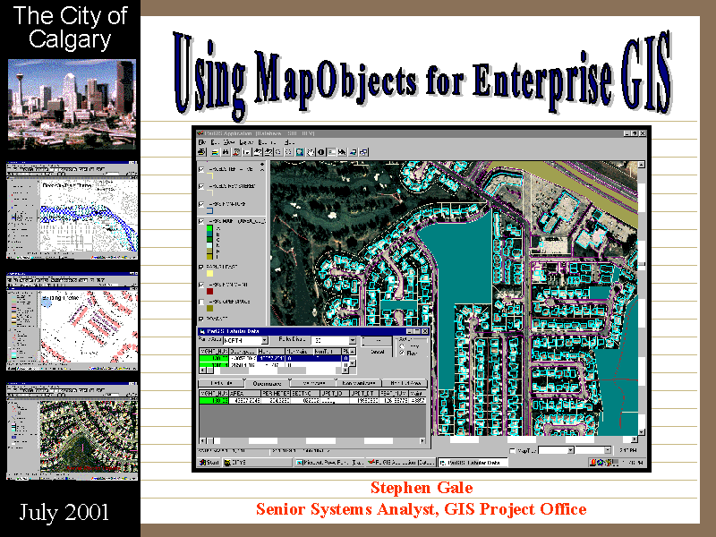
Table of Contents
Overview
This paper contains notes for my PowerPoint presentation at the 2001 San Diego User Conference. It
contains a summary of how GIS and, in particular, MapObjects is being used for the
delivery of GIS at The City of Calgary. We hope to share some of our experiences, our development
environment, our methodology, and our findings.
In June 1999, The City of Calgary selected Esri as our Enterprise GIS tool.
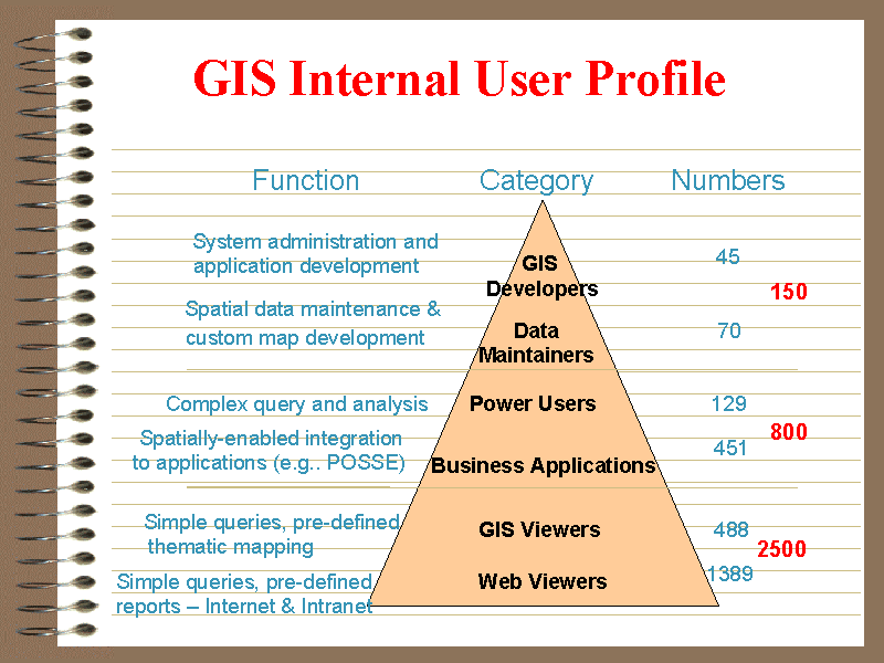
- Our expected GIS user base was:
- well over 2500 internal GIS viewers
- over 200 GIS power users
- 800 business application users with integrated GIS
- over 150 spatial data creators and maintainers
- delivery to the public over the web
- Our preferred environment had the following characteristics:
- all spatial data (with some exceptions) would be stored in the new GIS software's unified database
- some existing applications would view and/or update the new GIS database without off-line translation
- some spatial data would be maintained using the new GIS tools
- most viewing and analysis would be done with the new GIS tools
Two years ago, the GIS Project Office was formed to "provide the right information to the right person at the right time with the right resources".
- We currently have:
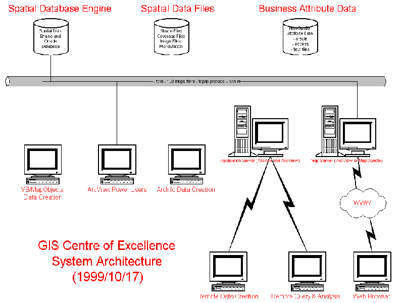
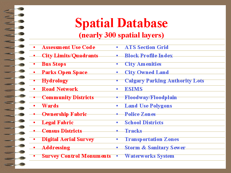
- nearly 300 replicated spatial layers and annotation residing in our Esri SDE database
- 5 spatial layers created and maintained directly in the SDE database using MapObjects (with 10 more
layers being maintained soon)
- regularly have 100 connections to the SDE during business hours
- nearly 300 trained ArcView users
- over 450 Planning and Building business users displaying maps
- dozens of Visual Basic/MapObjects business users
- many internal web browser users viewing MapObjects/IMS and ArcIMS maps and linked business data
Our GIS Environment
GIS Tools
At a high level, The City of Calgary uses the following products:
- ArcView 3.2 for spatial analysis. A few applications:
- allow Animal Services to determine the most effective routes for their staff
- ByLaw Redistricting to summarize block face census data to define ByLaw Enforcement Areas
- Community Profile produces the annual Community Profile documents, plus allows predefined queries against provincial, federal, and civic census
- EMS/Police/Fire allows address lookup across all GIS layers to capture the latest subdivision construction
- Ward Redistricting to summarize block face census data to redefine ward boundaries
- ArcInfo 8.0 for batch spatial data conversion
- a sequence of batch jobs that load Microstation files to the SDE, including (but not limited to):
- Road Network
- Legal Parcels
- Ownership Parcels
- Waterworks
- Storm
- Sanitary
- Streets
- Digical Aerial Survey Digitized Mapping
- etc
- this data is available to any ArcView user, as well as being available for the web mapping applications
- MapObjects/IMS Internet Start Applications (to be replaced with ArcIMS solutions)
- address/intersection search
- turn layers on or off
- thematic mapping of census data
- complex queries of assessment data
- display Block Profile and Registered Plans scanned images
- ArcIMS 3.0 for Internet Map Serving
- allows Aldermanic staff to lookup political tabular data, plus maps, mailing labels
- produce an image of a selected parcel and associated annotations in response to CityOnline clients (going into Beta test now)
- Integration with existing business applications
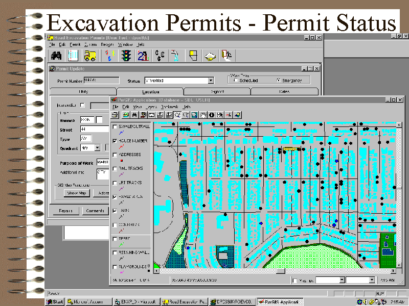
- display SDE data through the Permitting application. Maps are usually limited to an few blocks around a particular parcel
- display SDE data within ArcView through a real-time link to the Novalis/Assessment application
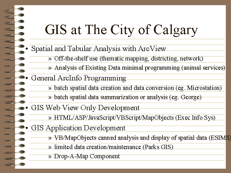
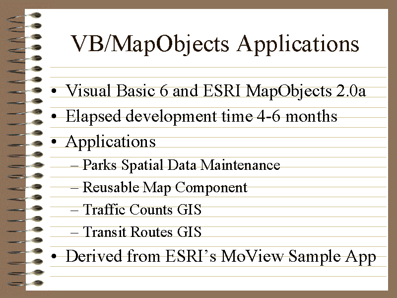
- Visual Basic 6/MapObjects 2.0a for business application development (many of these create and
maintain the spatial data directly within the SDE)
- Environmental Sites Inquiry
- Parks openspace maintenance
- 'Drop-a-Map' Component
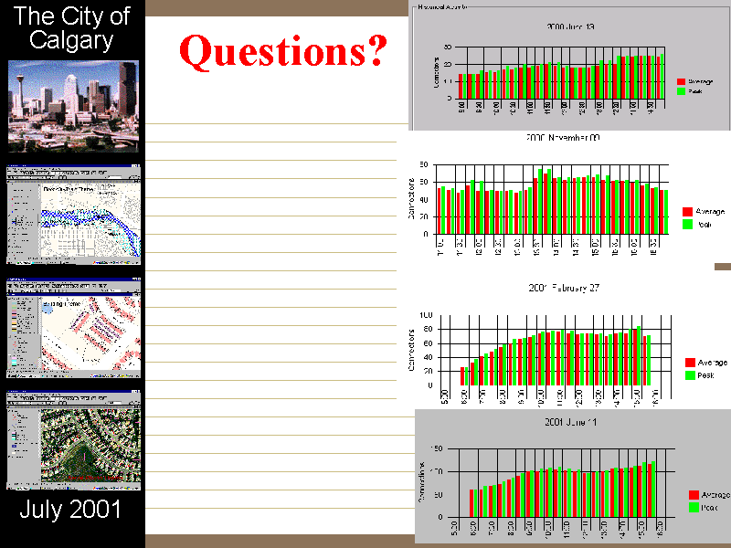
- Traffic Counts (final testing)
- Transit Routes Analysis and Maintenance (final testing)
- SDE 3.0.2.2 for a spatial data repository
- nearly 300 spatial layers and annotations
- 5 spatial layers being maintained directly in SDE (with 10 more layers being maintained soon)
- Shape Files for power user analysis
- giga-bytes of spatial data for power user analysis
This presentation focuses on the Visual Basic/MapObjects applications and the associated development environment, with a focus on the Drop-a-Map component. This component enables any non-GIS Visual Basic application to include a map with a minimum of development effort.
MapObjects Applications
Since acquiring Esri, we have used Visual Basic with MapObjects to develop a variety of business
applications. We have found that MapObjects provides an excellent set of tools for viewing and analyzing
spatial data, and good features for spatial data creation and maintenance.
Some of the MapObjects applications developed to date include:
- Environmental Site Inquiry
- nightly batch load of new/updated sites
- mapping inquiry
- Census Point-In-Polygon Processing
- performs spatial point-in-polygon lookup for newly entered census records (for ward, community, census district, public school district, and separate school district)
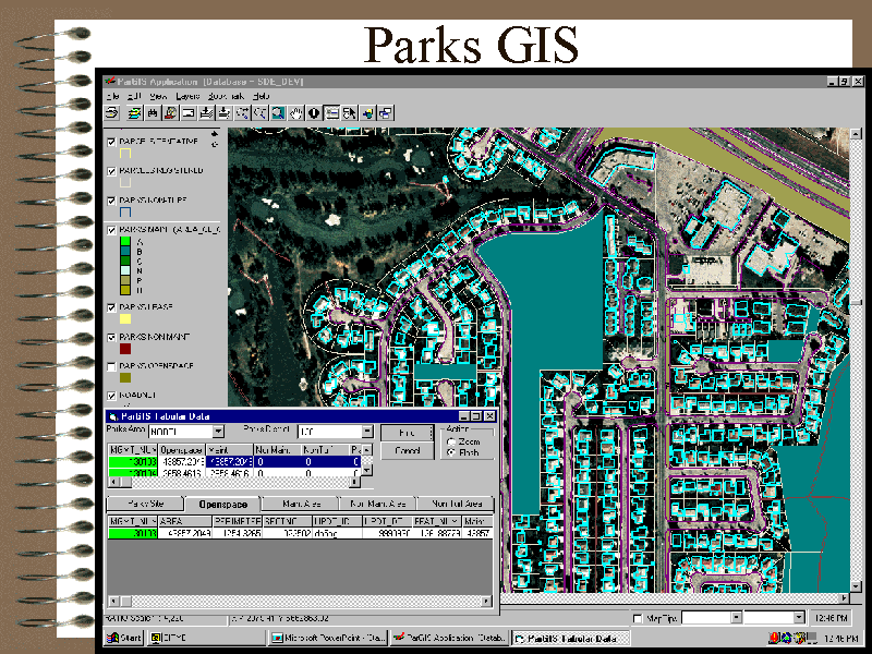
- Parks GIS
- creates and maintains Parks Openspace areas, with links to Oracle tabular information
- spatial data is maintained directly within the SDE
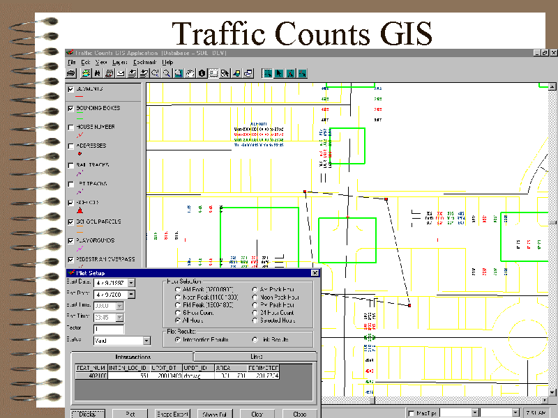
- Traffic Counts GIS
- creates and maintains locations of intersection and road segment studies
- displays and plots traffic count results for peak or specified time periods
- spatial data is maintained directly within the SDE
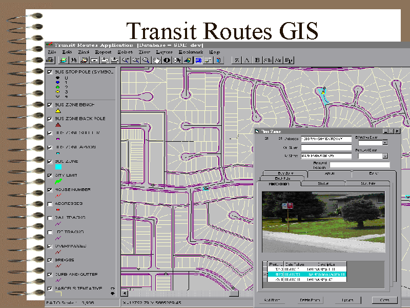
- Transit Routes GIS
- creates and maintains transit inventory (bus stops, zones, shelters, etc) and route information
- allows for a variety of analysis (route calculation, walking distance, etc)
For the desktop applications, we tried to give these applications the same basic look and feel, with easy spatial data creation tools and attribute entry.
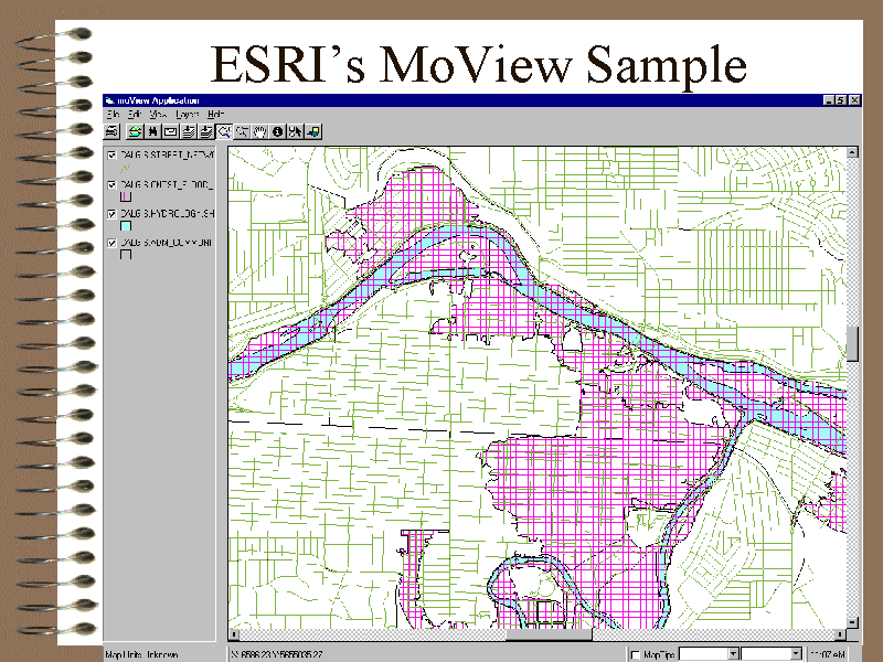
As you will see shortly, we used the Esri sample application MoVIEW2.VBP as the foundation for our applications.
Development Environment
Standards and Quality Control
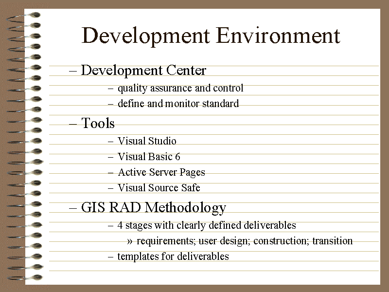
The City of Calgary's Information Technology Services (ITS) use Visual Studio as their development standard. Visual Basic is the application development language of choice, with Active Server Pages hitting VB 3-tier DCOM components for thin client and web delivery. All source code is maintained within Visual Source Safe.
Thus, these were the tools of choice for the GIS Project Office. At the present time, MapObjects applications are delivered as 'fat' Client/Server apps (with the exception of the web applications).
The Development Center of ITS provide the quality assurance and quality control necessary to deliver standard applications with a common look and feel (both the user interface and the coding style). Project and design reviews are performed early in the project to ensure that technology is used in a standard method, while code reviews are performed as development is nearing completion.
Methodology
The GIS Project Office required a methodology that would facilitate the delivery of GIS applications in a short time frame. We wanted to deliver some basic functionality, then improve it by adding additional features, again in a short timeframe.
When we acquired the Esri suite of products, we knew they would facilitate the prototyping process to help our understanding of the business function. In addition, we knew that many of the prototypes could also be robust enough to form the foundation for the production application.
Since many of these applications were expected to use existing spatial data for viewing, analysis, and thematic mapping, the rigor and length of the existing Development Methodologies may be inappropriate.
Various Rapid Application Development approaches were reviewed, and the most relevant deliverables were extracted and incorporated into the GIS/RAD methodology.
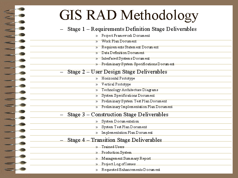
The methodology was divided into four stages. See Appendix A for an overview of the deliverables for the methodology:
- Stage 1 - Requirements Definition
- Stage 2 - User Design
- Stage 3 - Construction
- Stage 4 - Transition
Each stage of the methodology has clearly defined deliverables. However, the length and content is dependent upon the application. Each deliverable may range from a simple Powerpoint presentation or a one page summary for simple applications, to multi-page reports and more formal deliverables.
Templates for these deliverables were distributed to help ensure GIS Office project teams were approaching projects from the same direction. Over the last two years, these documents have been revised and improved. It's nice having a foundation of examples that can be copied and modified: they provide a 'running-start' for a new application. See Appendix B for the table of contents of these deliverables.
The project framework document is one of the key deliverables as it sets the direction for the project.
We have found that weekly status reports help keep a project moving. Without this weekly commitment, projects may wander.
Experiments with Code Generation
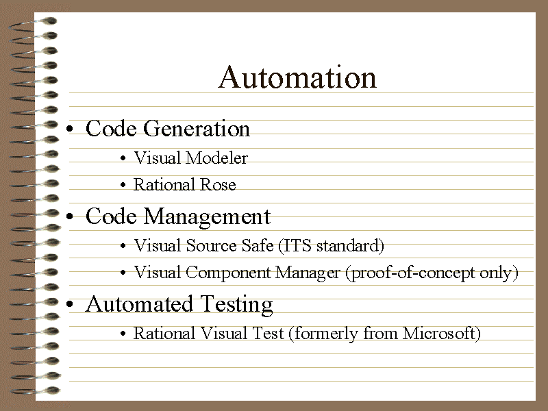
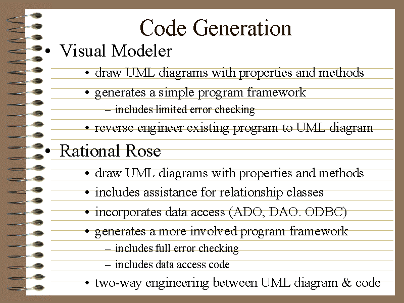
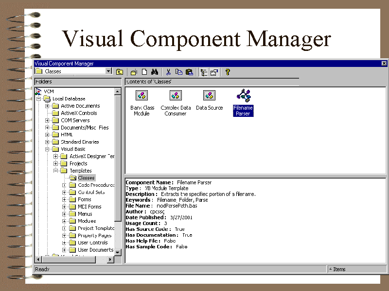
We have briefly experimented with automated code generation. Both Visual Modeler and an evaluation version of Rational Rose have been used to generate code templates from Unified Modeling Language (UML) diagrams. Small portions of the Visual Modeler code have been used within Traffic Counts and Transit Routes GIS application.
We felt that Visual Modeler saved time by clarifying which methods and behaviours were required within the classes by using the UML, with some limited benefits due to code generation. The code generated by Rational Rose (which included some data access and significant error checking) was very nice. Rose also has the ability to revise the UML based on code changes. We would like to follow-up on the Rational Rose approach to code generation as time permits.
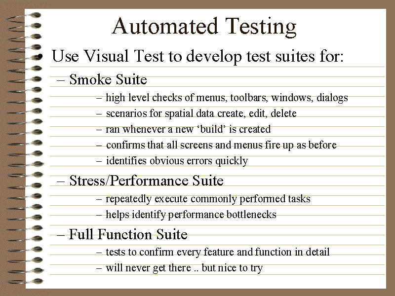
Experiments with Automated Testing
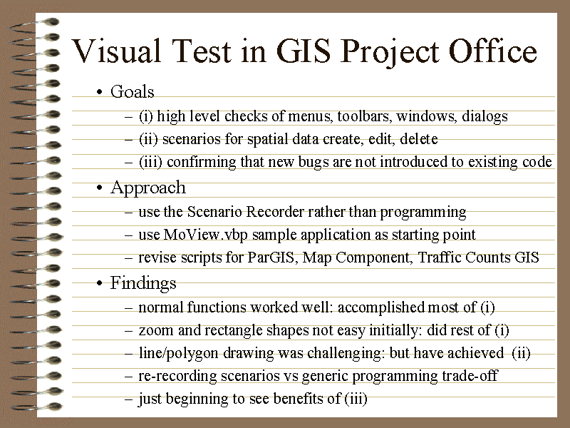
We have used some limited automated testing. We have developed automated test scripts for MoView, Parks GIS, the Drop-a-Map Component, and for Traffic Counts GIS. These scripts confirm basic functionality, as well as some limited regression and stress/performance tests.
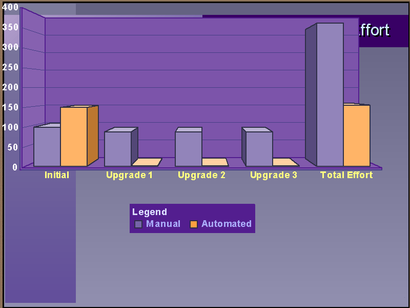
We found that developing test scripts is like a separate development effort. It requires planning and manpower. It will not find bugs in new code, but it will help identify new bugs in code already written.
It is great for regression testing (ensure that a bug that has been removed does not return), as well confirming that basic functions work after an enhancement is implemented.
I believe the benefits begin to accrue as soon as the first piece of user interface is considered complete. If an automated script is recorded for that component, it can be reused as further development proceeds, thus ensuring that future coding does not break what already works.
As an example, when we Beta tested MapObjects 2.1, we ran an automated test script against the Esri sample program MoVIEW2. Within 30 seconds, the screen turned black during a test of the 'redlining' functions. The Esri MapObjects team corrected the problem for the next Beta release.
Application Design
Various Esri sample programs were used to jump start our Visual Basic/MapObjects development effort. In addition, a variety of books and magazines were scrutinized.
MoVIEW2 as a Foundation
Esri’s MoVIEW2 sample application provided a wealth of GIS functionality. This Visual Basic/MapObjects application includes:
- panning/zoom in/zoom out/full extent
- legend/symbology
- add/remove new GIS layers from: shape files, GIS database, microstation, etc
- add/remove image layers: orthophotos, TIF, etc
- redlining/markup
- find/identify features
- address matching
- spatial selection, with optional saving of results to a new shape file
If you look at any of our GIS Visual Basic/MapObjects applications, you will see these features as the foundation. We needed to add some basic error checking, but the code seems very stable. If you have not
had a chance to try it out, it is installed in folder
C:\Program Files\Esri\MapObjects2\Samples\VB\MoView2
Edit On-Screen Shapes
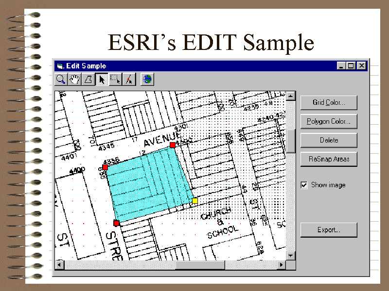
The EDIT.VBP sample provided a jump-start approach to giving the user the ability to drawing new spatial information. This example allows the user to draw a polygon, add/move/delete vertices, and save features (en-mass) to a shape file.
The basic concept (encapsulated within the clsEditLayer class) has been used in our Parks GIS (Openspace creation), Transit Routes (bus stop and bus zone creation), and Traffic Counts (intersection and study location creation).
This program is installed in folder
C:\Program Files\Esri\MapObjects2\Samples\VB\Edit
ObjectTable for Editing the SDE Database
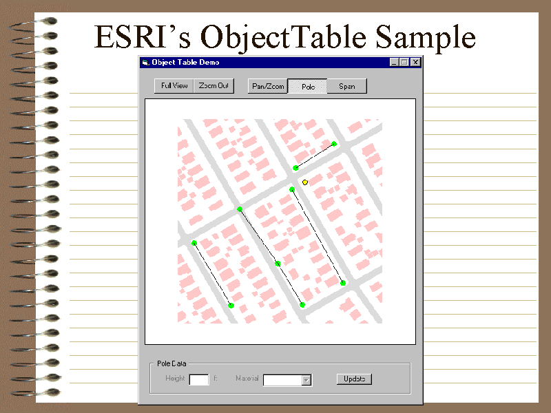
The ObjectTable sample application provided an excellent template for spatial data creation and entry of associated attribute values in a seamless manner, while directly editing the GIS SDE database or a shape file. (We did not want to create and maintain spatial data with Coverages using ArcInfo 7, followed by replicating the coverages to the SDE on a regular basis).
In addition, the ObjectTable program (found at Esri's web site at http://gis.Esri.com/arcscripts) provided a great example of inheritance in Visual Basic using 'containment and delegation' for any Object Oriented developers.
FindClosest for Snapping
The FindClosest sample routine (also found at Esri's web site at http://gis.Esri.com/arcscripts) provided the foundation for 'snapping' to features with the SDE. Although not perfect, it was sufficient to deliver business results (ie. spatial data creation and maintenance) to our clients in a reasonable timeframe.
LinePoint
The LinePoint sample application (again found at Esri's web site at http://gis.Esri.com/arcscripts) provided key insights to using MapObjects.
Books/Magazines
The following are the major resources we have used:
- Visual Basic 6 Client Server How To
- Visual Basic 6 Database How To
- Visual Basic 6 How To
- Visual Basic Source Library
- Visual Basic Programmer’s Journal
Our Map Component
Functional Overview
In an effort to deliver commonly used functionality to other (non-spatial) Visual Basic applications, the GIS Office modified the Parks application to be a reusable Map Component, with read-only capabilities.
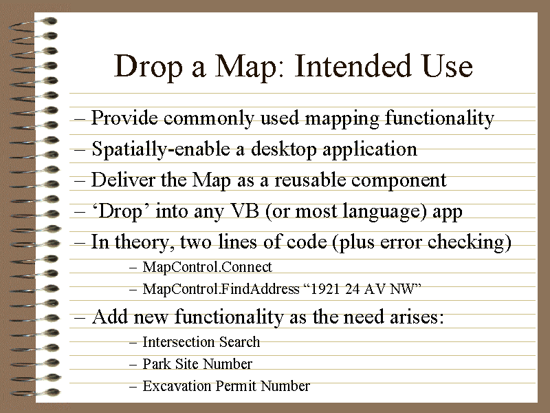
This Map Component is intended to add the following features with a minimal of GIS programming knowledge:
- pan/zoom/full extent
- address search
- intersection search
- read-lining
- spatial selection
- park site number search
- permit number search
- X,Y Search
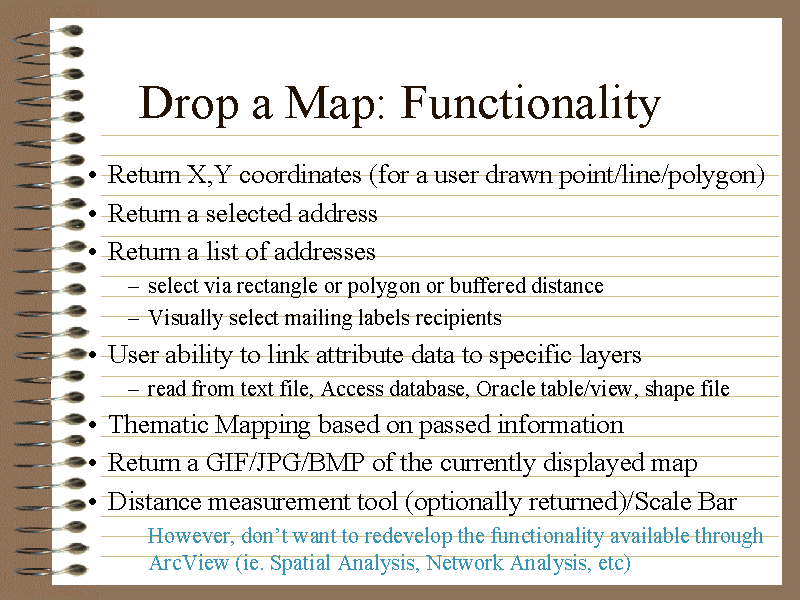
- Return X,Y coordinates (for a user drawn point/line/polygon)
- Return a selected address
- Return a list of addresses
- Select a list of addresses via rectangle or polygon or buffered distance
- Thematic Mapping based on passed information
- Return a GIF/JPG/BMP of the currently displayed map
Using the Component
Our goal was to minimize the effort to spatially-enable an application. Thus, the following
simple lines of code (plus error checking) are required to use the Map Component:
- Connect
- Address Search
- MapControl.FindAddress “1921 24 AV NW”
- Intersection Search
- MapControl.FindIntersectionSearch “University DR NW”, "Crowchild TR NW"
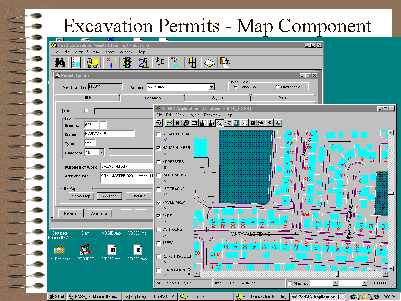
This component is currently being rolled out to 90 users, with a link to the Parks asset management system. It is also being user-tested in the newly developed Excavation Permits application.
Technical Overview
Our goal was to create a reusable map component that could easily be added to any Visual Basic
application. In the Microsoft world, there are several options, with pros and cons for each
approach.
- Develop as an ActiveX Control
- Pros
- simply add to the VB toolbox
- drag-and-drop onto the form
- simple to interface
- Cons
- adds a larger footprint to the application
- if the control crashes, it takes the underlying application with it
- cannot be run standalone
- Develop as an ActiveX Component
- Pros
- simply add to the VB references
- if the component crashes, does not take the underlying application with it
- Cons
- cannot simply drag-and-drop onto form
- slightly more difficult to interface
- cannot be run standalone
- Develop as an ActiveX EXE
- Pros
- simply add to the VB references
- if the component crashes, does not take the underlying application with it
- can be run standalong
- Cons
- cannot simply drag-and-drop onto form
- slightly more difficult to interface
We chose to implement as a late-bound ActiveX EXE. The program can be run standalone, or fired up from
another application. Adding a real-time link between a late-bound component and the application was a
bit of a challenge since events are not exposed directly. The technique used is called 'using a Change Event with Callback', and works very well.
In summary, here is how this technique works: the client programmer adds
a Label onto a form and sets the Label's Visible property to False. The
client programmer then adds an Event Handler for the Label's Change
event. A reference to the Label is passed to the Map Component when the
connection is first made. In the Map Component (after the user has
selected a Point, Single Address, etc), the last step is to assign a
value to the Label field which reflects the type of selection. Back in
the client, the Label's Change event fires, and knows which info to
pick up from the Map Component based on the value of the label.
Our Next Steps
Currently at The City of Calgary we are busy planning for
the deployment of ArcGIS (ArcInfo 8.1, ArcView 8.1, and ArcSDE 8.1). We want a clear understanding of ArcEditor's spatial data creation and maintenance functionality. Then our focus will probably shift to VB, VBA, and ArcObjects development where appropriate.
The future of MapObjects depends upon Esri. We hope that a new version of MapObjects will be developed
using ArcObjects, but expose the same (or very similar) behavior as MapObjects.
Conclusion
The Esri sample applications provided an excellent jump-start for our MapObjects application
development effort. GIS application development now takes a reasonable timeframe: how long, of course, depends upon the size of the application. However, MapObjects is a very effective set of objects for rapid development, and it is relatively easy of use.
The use of the Map Component helps minimize the learning curve in spatially-enabling an application.
Acknowledgements
- GIS Project Team
- Robert Eason, Manager
- Dianne Haley, GIS Business Specialist
- Audrey Stamm, GIS Business Specialist
- Glenn McKean, GIS Business Specialist
- Gord Rasmussen, GIS Data Administrator
- Bill Findlay, Outstanding Business User
- Larry Williams, GIS Analyst
- Brad Smith, GIS Senior Programmer Analyst
- Beverly Barthel, GIS Senior Programmer Analyst
- Jim O'Neil, GIS Senior Programmer Analyst
- Rob Goss, GIS Senior Programmer Analyst
- Beverley Greyeyes, Senior Programmer Analyst
- Bryan Barnes, Senior Programmer Analyst
- Greg Parsons, Senior Database Analyst
- Carl Uschold, Senior Technical Analyst
- ITS Team
- Ron Scutchings
- Ken Johannesson
- Mark Lunn
- Wayne Yip
- Vin Bhola
- Mike Pears
- Dallas Smith
My apologies for not including the many other people who have helped make the GIS Project of "The GIS
Center of Excellence".
Appendices
Appendix A - GIS RAD Overview
The GIS Project Office required a methodology that would facilitate the delivery of GIS applications in a short time frame. As many of these applications were expected to use existing spatial data for viewing, analysis, and thematic mapping, the rigor and length of the existing Development Methodologies may be inappropriate.
Various Rapid Application Development approaches were reviewed, and the most relevant deliverables were extracted and incorporated into the GIS/RAD methodology.
The methodology was divided into four stages:
- Stage 1 - Requirements Definition
- Stage 2 - User Design
- Stage 3 - Construction
- Stage 4 - Transition
Each stage has clearly defined deliverables. However, the length and content is dependent upon the application. The deliverable may range from a simple Powerpoint presentation or a one page summary for simple applications, to multi-page reports and more formal deliverables. However, the descriptions below convey the intended contents.
Stage 1 – Requirements Definition Stage Deliverables
- Project Framework Document:
-
The Framework Document is developed during the initial meetings with the clients. These initial meetings may also result in an early version of the prototypes. At a high level, the document outlines stakeholders, objectives, what is in scope and out-of-scope, benefits, constraints, key deliverables, project approach, resource and training requirements, key spatial data created and used, GIS functionality, technology requirements, implementation timeframes, and risks. The framework should include a preliminary Context Diagram.
- Work Plan Document:
-
The Detailed work plan document reaffirms the project objective and the approach for the project. The work plan outlines tasks, resources, milestone dates, and review meetings. The document also describes the deliverables for each Stage of the Project, but tailored for the project. The work plan drives the Project 98 plan, so a Gantt Chart from Project should be attached.
- Requirements Statement Document: (what the system should do)
-
The Functionality Description Document outlines in as much detail as possible ‘what’ needs to be performed by the system: the functional requirements. But the ‘how’ of the system can be addressed here if it helps to clarify the concepts and understanding (our goal is to develop a working system). In addition to the functional requirements, the technology requirements, performance requirements, and interfacing should be identified. A revised Context Diagram should be attached.
- Data Definition Document:
-
The content of the Data Definition Document depends upon the size and complexity of the application. For many of the GIS analysis type applications, the document may just simply identify the sources of existing data. For data creation and maintenance applications, a more involved entity relationship diagram may be required. For a ‘business reengineering’ application, a complex data modeling exercise may be undertaken. An appropriate data model should be attached.
- Interfaced Systems Document:
-
One significant factor governing the complexity of a system is the number of interacting systems. Notifications and dependencies upon existing or new data need to be identified and a plan for handling the interface needs to be outlined. Approaches may range from simple e-mail notifications that data has changed, through to batch interfaces or real-time feeds. A finalized Context Diagram should be attached.
- Preliminary System Specifications Document: (how the system should do it)
-
The System Specifications Document describes a first cut at ‘how’ the proposed solution for the system will be programmed. This includes preliminary descriptions of user screens, data files, and internal processing. A description of the system architecture will be itemized, and how it addresses technical and operational performance issues. A Decomposition Diagram (high level tasks) and a System Diagram (interaction of tasks and data) should be attached.
- Requirements Definition Signoff:
-
All deliverables for this stage will be assembled and presented to the Client, with an attached memo. The client will sign-off that the stage is complete, and that the next stage can proceed.
Stage 2 – User Design Stage Deliverables
- Horizontal Prototype:
-
The Horizontal Prototype will make available all screens with a very minimal of functionality. Some screens will display data, others will be for layout format only. The Horizontal Prototype serves as a quick demonstration that the screen format and layout is appropriate. An initial version of the horizontal prototype may have been developed during the initial client meetings. Horizontal Prototypes must be reviewed frequently by the client and improved based on feedback.
- Vertical Prototype:
-
The Vertical Prototype will demonstrate that the proposed approach will perform acceptably in the proposed environment. The Vertical Prototype serves as a quick demonstration as 'proof of concept' that the technology and functionality can be delivered. The prototype will consist of one or more screens with all basic functionality (add, update, delete, navigation between records), and minimal error checking. On occasion, an initial version of the vertical prototype may have been developed during the initial client meetings. Vertical Prototypes must be reviewed frequently by the client and improved based on feedback
- Technology Architecture Diagram:
-
The Technology Architecture Diagram will pictorially show the relationship of the system components (client machines, database servers, file servers, application servers, etc) and the network architecture.
- System Specifications Document: (how the system will do it based on the prototypes)
-
The System Specifications Document describes in detail ‘how’ the proposed solution for the programmed. This includes all user screens, data files, and internal processing that is required. A description of the system architecture will be itemized, and how it addresses technical and operational performance issues.
- Preliminary System Test Plan Document:
-
The Test Plan Document will describe the testing objectives, as well as the technical and functional acceptance criteria to judge the system. The test environment, resources, and schedule will be described. The test data, test cases, and test scenarios to meet the each test objective and acceptance criterion will be listed. Regression points, as well as stress test data will be identified.
- Preliminary Implementation Plan Document:
-
The Implementation Plan Document will describe the preliminary implementation schedule. Administration procedures are defined for setup of the client and server machines, as well as any necessary test procedures will be described. Installation procedures and activity checklists will be included.
- User Design Stage Signoff:
-
All deliverables for this stage will be assembled and presented to the Client, with an attached memo. The client will sign-off that the stage is complete, and that the next stage can proceed.
Stage 3 – Construction Stage Deliverables
- System Documentation:
-
The System Documentation will describe the developed program (whether AecView/Avenue, Visual Basic Programs, ArcInfo/ArcObjects functionality, HTML forms, VBScript and ActiveX Components). Any reusable components will be described in detail, and made available via the GIS Web Page. Security as implemented will be described.
- System Test Plan Document:
-
The Test Plan Document will describe the testing objectives, as well as the technical and functional acceptance criteria to judge the system. The test environment, resources, and schedule will be described. The test data, test cases, and test scenarios to meet the each test objective and acceptance criterion will be listed. Regression points, as well as stress test data will be identified.
- Completed, Tested System (ready for acceptance test):
-
The Esri and GIS Team will deliver a completed and tested system ready for acceptance test. This system will have been tested as much as possible within the timeframe. We anticipate minimal problems occurring during the acceptance test.
- Test Results Document:
-
Based upon the System Test Plan Document, the pass/fail status of each test case in the Acceptance Criteria will be listed and summarized. This document will be provided to the Client for their review and comparison to the acceptance criteria. The acceptance criteria can be adjusted slightly during the analysis of results, provided that both the Client and the GIS Team are in agreement.
- User Signature (that system performs as agreed):
-
By signing, the user agrees that the system meets the acceptance criteria as outlined in the System Test Plan Document, or any subsequent agreements.
- Implementation Plan Document:
-
The Implementation Plan Document will describe the final implementation schedule. Administration procedures are defined for setup of the client and server machines, as well as any necessary test procedures will be described. Installation procedures and activity checklists will be included. A plan for moving the application to a maintenance mode will be included (ie. warrantee period, plans for bug fixes and enhancements, and operations)
- Construction Stage Signoff:
-
All deliverables for this stage will be assembled and presented to the Client, with an attached memo. The client will sign-off that the stage is complete, and that the next stage can proceed.
Stage 4 – Transition Stage Deliverables
- Trained Users:
-
Because the system was developed with the client’s full participation, the Client will develop the training material. Being a part of the prototype development as well as the construction of the application has enhanced their understanding of the system.
- Production System:
-
The Production System will be an Application that meets the objectives laid out in the Framework Document. It will be tested and signed off from the previous stage. It will be implemented according to the Implementation Plan
- Management Summary Report:
-
The Management Summary Report will provide an overview of the system, lessons learned, development time and cost comparison between estimates and action. The report will include a consolidation of the deliverables into a final report to be presented to the Client. Throughout the project, the list of enhancements and log of issues can be used to identify the most appropriate next steps for the Project.
- Transition Stage Signoff:
-
All deliverables for this stage will be assembled and presented to the Client, with an attached memo. The client will sign-off that the application is complete.
On-Going Deliverables
- Status Reports:
-
Weekly status reports will be prepared for the weekly half-hour team meetings, and will list:
- tasks completed during the week
- tasks planned but not completed during the week
- unplanned tasks performed during the week
- tasks planned for the next week
- log of issues, their status, and who is responsible
- requested enhancements
- Project 98 Gantt Chart:
-
A Gantt chart, which was derived from the Stage 1 Work Plan Document, will be delivered with the status report. The Gantt Chart will be updated weekly to reflect progress to date. It will also be adjusted to reflect revised end dates as required.
- Project Log of Issues:
-
During the project, technological, software, and people-ware issues will arise. This log will list a description of the issue, an agreed upon course of action, the person who is responsible for the action, and the date that action is to be taken by. This will serve as feedback for proposing future direction for the project, as well as a basis for the 'lessons learned' section of the Mangement Report.
- Requested Enhancements Document:
-
During the development and subsequent testing of the system, several enhancements will be identified. This document will itemize each of the requests. The client will assign a 'level of importance' to each item (A=critical; B=required; C=nice to have). Within each 'level', the Client can set a priority to each request. Requests in this document can be handled as a separate initiative.
Appendix B - GIS RAD Deliverables Table of Contents
Templates for the GIS RAD deliverables were distributed to help ensure everyone was approaching projects from the same direction. As we gained experience, the documents and their contents were refined to what they are today.
Appendix A contains an overview description of the deliverables, and this appendix contains the table of contents.
Stage 1 – Requirements Definition Stage Deliverables
- Project Framework Document:
- Application Name
- Application Description
- Stakeholders
- Preliminary Objectives
- Preliminary Scope
- In Scope Items
- Out of Scope Items
- Expected Benefits
- Constraints
- Project Approach
- Key Deliverables
- Training, Testing, Documentation
- Resources
- Foundation Spatial Data Created
- Foundation Spatial Data Used
- Other Data Created/Maintained/Used
- Technology Requirements
- GIS Functionality Expected
- List of Interfaced Systems
- Implementation Timeframes
- Risks and a Management Plan
- Work Plan Document:
- Project Background (reference the Framework document)
- Confirmed Objectives
- Final Scope
- In Scope Items
- Out of Scope Items
- Approach (tailored for this project)
- Roles and Responsibilities
- Stages and Deliverables
- Description of Deliverables (tailored for this project)
- Requirements Statement Document: (what the system should do)
- Project Background (reference the Framework and Workplan documents)
- High Level Description
- Functional Requirements
- Technical Requirements
- Performance Requirements
- Interfacing Requirements
- Data Definition Document:
- Project Background (reference the Framework and Workplan documents)
- Overview
- Attributes
- Data Constraints
- Primary Keys
- Foreign Keys
- Oracle Linked Tables
- Source Data Descriptions
- Data Conversion, Batch Load, Initial Setup
- Data Security
- Interfaced Systems Document:
- Project Background (reference the Framework and Workplan documents)
- Summary of Data Requirements
- Read-Only Systems
- Read-Only System #1
- Description
- Data Read
- Method of Access
- Authorizations Required
- Read-Only System #2
- Updated Systems
- Updated System #1
- Description
- Data Read
- Data Updated
- Method of Access
- Authorizations Required
- Updated System #2
- Preliminary System Specifications Document: (how the system should do it)
- Project Background (reference the Framework and Workplan documents)
- High Level Description
- Business Rules
- Objects, Attributes, Behavior
- Preliminary Class Design and UML
- Preliminary Module Design and UML
- Preliminary Form/GUI Design and Functionality
- Printing and Plotting
- Quality Control
Stage 2 – User Design Stage Deliverables
- Horizontal Prototype:
- Description of Prototype
- Screen Prints
- ArcView Project
- Data Used
- Results
- Lessons Learned
- Vertical Prototype:
- Description of Prototype
- Screen Prints
- ArcView or MapObjects Project
- Data Used
- Results
- Lessons Learned
- Technology Architecture Diagrams:
- Context Diagram
- Network Diagram
- UML Diagrams
- Data Flow Diagrams
- System Specifications Document: (how the system will do it based on the prototypes)
- Project Background (reference the Framework and Workplan documents)
- High Level Description
- Business Rules
- Objects, Attributes, Behavior
- Class Design and UML
- Module Design and UML
- Form/GUI Design and Functionality
- Printing and Plotting
- Quality Control
- Preliminary System Test Plan Document:
- Project Background (reference the other documents)
- Overview of Test Procedure
- Requirements
- Preliminary Test Plans
- Preliminary Acceptance Criteria
- Preliminary Test Cases
- Preliminary Test Scenarios
- Preliminary Test Data
- Preliminary Stress Tests
- Preliminary Performance Tests
- Preliminary Implementation Plan Document:
- Project Background (reference the other documents)
- Development/Implementation Tools
- Notification/Approval
- Deployment Dates and Locations
- System Requirements
- Storage Requirements
- Security Requirements
- Statement of Expected Performance Impacts
- Backup Procedures
- Contingency/Backout Plan
- Operations Training
- Data Preparation and Conversion
- Server Installation Procedures
- Deployment Package Preparation
- Client Installation Procedures
- Implementation Checklists and Timeframes
- To Development environment
- To Test environment
- To Production environment
Stage 3 – Construction Stage Deliverables
- System Documentation:
- Project Background (reference the Framework and Workplan documents)
- High Level Description
- Business Rules
- Objects, Attributes, Behavior
- Class Design and UML
- Module Design and UML
- Form/GUI Design and Functionality
- Printing and Plotting
- Quality Control
- System Test Plan Document:
- Project Background (reference the other documents)
- Overview of Test Procedure
- Requirements
- Test Plans
- Acceptance Criteria
- Test Cases
- Test Scenarios
- Test Data
- Stress Tests
- Performance Tests
- Implementation Plan Document:
- Project Background (reference the other documents)
- Development/Implementation Tools
- Notification/Approval
- Deployment Dates and Locations
- System Requirements
- Storage Requirements
- Security Requirements
- Statement of Expected Performance Impacts
- Backup Procedures
- Contingency/Backout Plan
- Operations Training
- Data Preparation and Conversion
- Server Installation Procedures
- Deployment Package Preparation
- Client Installation Procedures
- Implementation Checklists and Timeframes
- To Development environment
- To Test environment
- To Production environment
Stage 4 – Transition Stage Deliverables
- Trained Users:
- User Manual
- Windows Help File
- Training Material
- Production System:
- Deployment Package
- Executable
- DLLs
- INI files or registry settings
- Help Files
- Operations Manual
- Management Summary Report:
- Executive Summary
- Background (from project framework document)
- Review of Development and Methodology (based on Issues Log)
- Project Costs and Comparison to Estimate
- Next Steps (based on List of Enhancements)
- Recommendations (lessons learned)
- Project Signoff
- Log of Issues
- List of Enhancements
On-Going Deliverables
- Status Reports:
- tasks completed during the week
- tasks planned but not completed during the week
- unplanned tasks performed during the week
- tasks planned for the next week
- log of issues, their status, and who is responsible
- requested enhancements
- Project Log of Issues:
- Date Encountered
- Description
- Status
- Responsibility
- Date Resolved
- Comments
- Requested Enhancements Document:
- Date Requested
- Description
- Priority
- Responsiblity
- Comments
Appendix C - Creating an ActiveX Map Control
Creating a reusable GIS ActiveX Control Map in Visual Basic is straightforward when
using MapObjects. The following steps create
a project group (an ActiveX Control and a Test Project), adds the Esri Map Component to the
UserControl Form, adds an ImageList and a ToolBar, adds under fifty lines of code, drops the
new control into the Test Project, and Runs! "MAKE" the ActiveX Control and you can use
it in PowerPoint, Word, Excel, etc!
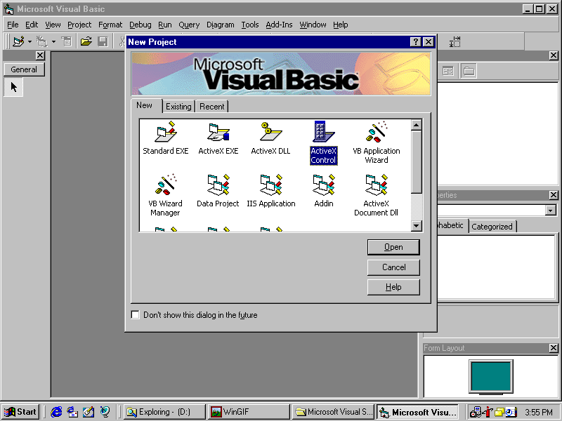
Creating an ActiveX Map Control
Open VB6 and Select ActiveX Control
Creating an ActiveX Map Control
Add a Second Project so You Can Test the Control
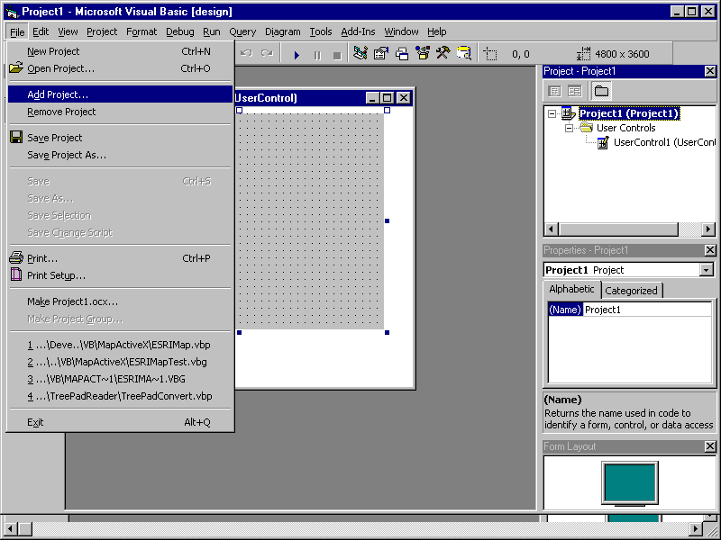
Creating an ActiveX Map Control
Select the Esri MapObjects Control from Projects/Components
(don't forget to add your shape files to the map properties)
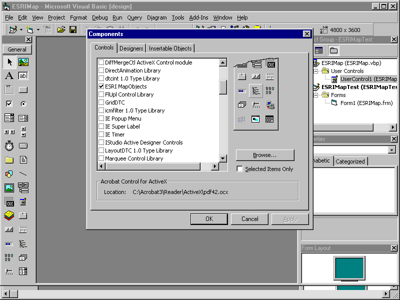
Creating an ActiveX Map Control
Add an ImageList and the Necessary Bitmaps
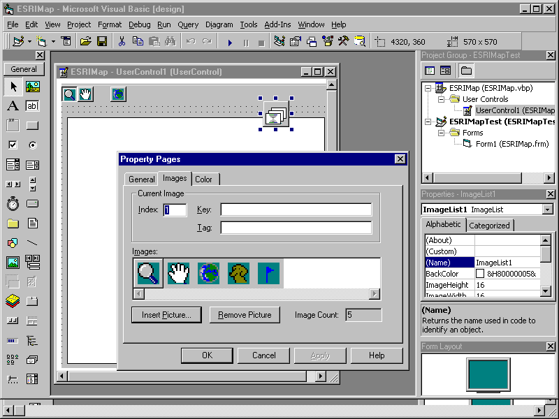
Creating an ActiveX Map Control
Add a ToolBar, link to ImageList and Images
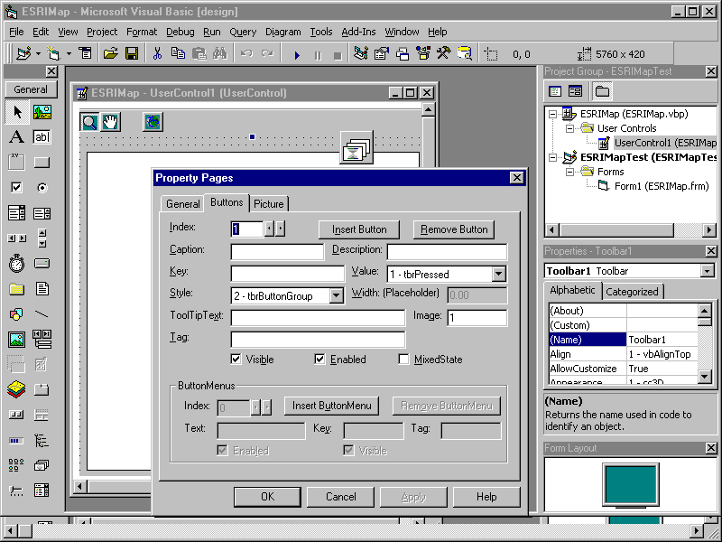
Creating an ActiveX Map Control
Add Code (22 Lines)
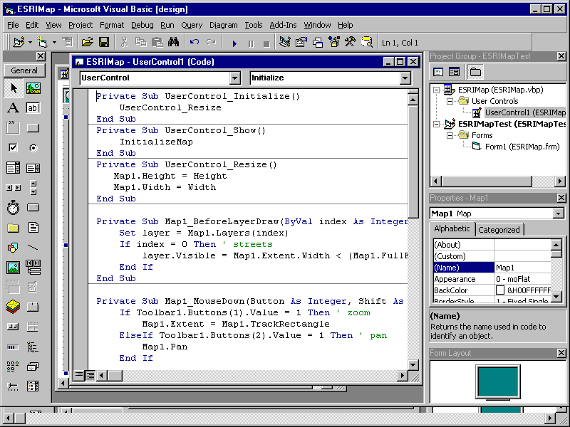
Creating an ActiveX Map Control
Add Remaining Code (25 Lines)
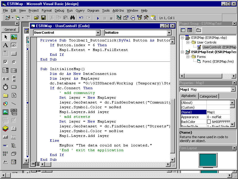
Creating an ActiveX Map Control
Add Your New Control to the Test Project Form
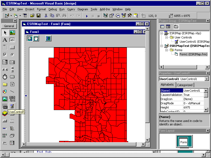
Creating an ActiveX Map Control
Run the Test Project to Try Out Your New Control
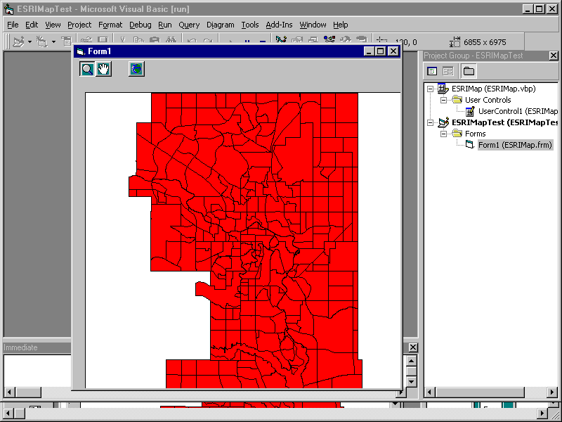
Creating an ActiveX Map Control
Make the ActiveX Control for Use in PowerPoint, Word, etc
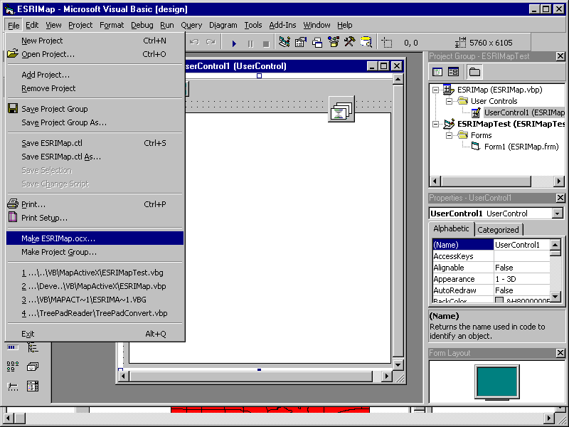
Appendix D - Visual Basic/MapObjects Application Gotchas
This appendix is extracted from Chapter 9 of our GIS Application Development Standards document. It contains features and obscure requirements that have caused application development difficulties in the past. They are provided here so that developers will be aware of them, and can therefore avoid them in the future.
- Always use the extents parameter when performing a union, intersect, xor, etc operations
- An SDE layer cannot be exported by the DBA utilities unless at least one entry exists
- It was previously thought that a new sde layer that is maintained by a Mapobjects program needs one record inserted manually via SQL. This has since proven incorrect. The next problem is likely the source of this misconception
- An SDE layer that is maintained by Mapobjects needs to have the SDE layer extents defined within the database by a DBA as the full area covered by the database. The problem is that if a record is created outside the current extents of the data, it will not be displayed. Occasionally exiting and restarting mapobjects will work, but not always
- A spatial select against the SDE with a self overlapping polygon returns no records (eg. a figure eight)
- A self overlapping shape will not be saved to the SDE
- A union of polygon and rectangle may result in a crash
- Use Map.Refreshlayer rather than Map.Refresh, if only one layer has changed, to increase speed.
- If you are updating the tracking layer, use Trackinglayer.Refresh rather than Map.Refresh to increase speed.
- When adding a layer, the numbering of layers changes. Thus refer to layers by name, rather than the index number.
- Use a date format of “YYYY-MM-DD” for Shapefiles. Use a date format of “YYYYMMDD” for SDE data
- MapObjects does not store the time portion of a date
- When using VB, dates appear to be stored in a MapObjects recordset differently than in an ADO recordset - or at least when retrieved, are in different formats. When retrieved from Oracle into an ADO recset: Date appears to be in format yy/mm/dd. When retrieved from Oracle into a MapObjects recset: Date appears to be in format yyyymmdd (or yymmdd). This problem also rears its head when updating the dates to Oracle. The dates must be manipulated differently before assigning the date to the recset field. When updating with 'no date' value: ADO recset accepts a null date. MapObjects recset will only accept zero's for a null date. This all could simply be a result of a setting either in Oracle or VB, but is unknown as yet.
- Adding a point feature and the feature and spatial tables would get updated but the business table would not. As it turned out this was occurring because the size of one of the fields was being exceeded causing oracle to kick out the update. The interesting thing is that VB or MapObjects didn't pass back the Oracle error (ORA-01438: value larger than specified precision allows for this column). Resized the attribute and the problem went away.
- Map.Refreshlayer - doesn't remove deleted features, so use this function carefully.
- the union of two points collections doesn't work. A null is returned instead of a points collection
- When adding the first record to a new SDE layer, occasionally the AddNew fails. The DBA may have granted access to the main table, but not to the underlying F (feature) and S (spatial) tables. To check if this is the case, follow these steps in SQL*Plus. The example uses the layer trpltcntg.traffic_count_intsn.
- desc trpltcntg.traffic_count_intsn;
- insert into trpltcntg.traffic_count_intsn values (1,1,1,1); <== this should work
- select count(*) from trpltcntg.traffic_count_intsn; <== should show one record
- select * from trpltcntg.traffic_count_intsn; <== should show the details
- select layer_id, table_name from sde.layers order by table_name; <== find the layer id number
- select * from trpltcntg.f300; <== no records in the feature table for the layer
- select * from trpltcntg.s300; <== no records in the spatial table for the layer
- desc trpltcntg.f300;
- desc trpltcntg.s300;
- insert into trpltcntg.s300 values (1,1,1,1,1,1,1);
- If this fails with insufficient privilege, then access has not been granted to the internal F and S tables. Request this from the DBA.
Stephen Gale, CCP, I.S.P.
Senior Systems Analyst
The City of Calgary, Calgary, Alberta, Canada


