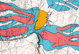
Figure 1: Example of the four zones (red, blue, yellow, white) in an Avalanche Hazard Map of Switzerland. Source: BFF/SLF 1984.
In winter 1999 many large avalanches endangered settlements, roads and railways in Switzerland. Thanks to the previously established avalanche hazard maps, loss of life and buildings was relatively small. Nevertheless the avalanches in 1999 showed some deficiencies in the existing avalanche hazard mapping procedure. To overcome these deficiencies, new numerical simulation methods in combination with GIS-technology were applied. GIS is used to identify and analyse avalanche release zones, to determine friction parameters along the avalanche track, to manage digital terrain data and finally to plot the hazard maps. Run-out distance, speed and deposits were calculated using different numerical simulation methods.
Avalanche hazard mapping is used by land planning authorities as tool to prevent buildings being constructed in areas that are endangered by avalanches. Since 1984 (BFF/SLF 1984), official guidelines for the definition and production of avalanche hazard zones exist in Switzerland. Four different zones, distinguished from each other by the impact force and the avalanche frequency, are used to define the degree of avalanches hazard. In the area of highest hazard (red), it is forbidden to build houses; in the moderate hazard zone (blue), houses are allowed to be built, but must be reinforced to withstand impact pressures of up to 3 t/m2. The yellow zone delineates areas where either avalanches occur very rarely, or where only a small impact of a powder snow avalanche is expected. The fourth zone (white) is considered to be free of avalanche hazard. Figure 1 shows an example of a Swiss Avalanche Hazard Map.
Figure 1: Example of the four zones (red, blue, yellow, white) in an Avalanche Hazard Map of Switzerland. Source: BFF/SLF 1984.
In the last century, two major avalanche winters struck the Swiss Alps. The first winter was in 1951 when about 1500 avalanches caused 98 deaths and damage to about 1500 buildings. In the winter of 1999, three large snowfall periods within one month led to about 1200 large avalanche events causing the death of 17 people in houses and on roads, significant damage to more than 1000 buildings and the blockage of many important traffic systems. Comparing these two winters shows that avalanche hazard mapping significantly contributed to reducing of the loss of life and damage to buildings despite a large increase in population and infrastructure in mountainous areas since 1951. However, the remaining number of deaths and damage clearly shows that the avalanche hazard mapping procedure in Switzerland has some deficiencies.
According to the Swiss Guidelines (BFF/SLF, 1984) the production of hazard maps must include the following steps:
Many of the above mentioned production steps could be improved by using Geographical Information Systems (GIS). This paper aims therefore, to describe the GIS-environment that has been developed recently in Switzerland for avalanche hazard mapping. It is focused mainly on the steps of avalanche dynamics calculations and analysis of the release conditions of extreme avalanches.
The existing avalanche hazard maps in Switzerland are based on avalanche dynamics calculations that use the so-called Voellmy-Salm model (Salm and others, 1990). This model is based on a hydraulic approach and contains only two friction parameters: μ (dry-friction) and ξ (turbulent or viscous friction). Since the middle of the 1990's, one- and two-dimensional numerical depth-averaged continuum models have been developed that resolve many of the shortcomings of the Voellmy-Salm model. However, numerical models also have drawbacks. For example, they require a more detailed description of the avalanche release zone. They also generate large amounts of output data that is difficult to analyse. To be able to manage these new requirements, the numerical models were integrated into a GIS-based user environment.
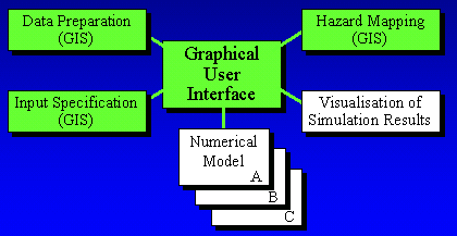
Figure 2: Overview of the GIS-environment for Avalanche Hazard Mapping. All green coloured topics are GIS-based, whereas the white topics were based on other software.
At the center of this environment is a graphical user interface that connects all the different elements of the avalanche dynamics calculations process. An overview of the system is given in Figure 2. The Topographical Data Preparation, the Input Specification and the Hazard Mapping tools are handled by ARC/Info, which also provides the main User Interface. The numerical simulation Models as well as their Visualisation tools are implemented using other software, but are directly connected to the User Interface. In the following section, the different tools are described in more detail.
A good digital representation of the topography is crucial for the accuracy of the model results. At present, in Switzerland a Digital Elevation Model (DEM) exists in a raster format with a spatial resolution of 25m (Swisstopo, 2001). Whereas this resolution is sufficiently accurate for open slope terrain, it is not accurate enough for steep gullies. Since most of the avalanche paths are at least partially in steep gullies, there is a strong demand for improving the quality of the DEM in these areas.
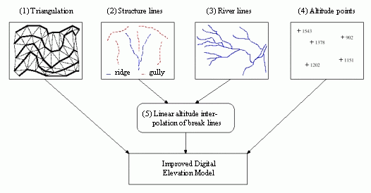
Figure 3: Flow chart of the improvement of the Digital Terrain Model based on the integration of contour lines, various breaklines with and without z-values and altitude points.
The Data Preparation module supports the integration of various structure lines and altitude points (see Figure 3) in combination with contour lines using the standard procedures of the ARC/Info-command "createtin". In addition, it provides a linear altitude interpolation tool for breaklines with missing z-values, since the existence of structure lines with linearly interpolated altitudes leads often to sufficient accuracy of the DEM in steep gullies. In a first step, the breaklines were intersected with the contour lines in order to get, for every intersection, the altitude. Using a C-program, the intermediate points of the structure lines were linearly interpolated according to their distance to the neighbouring contour lines. In the case of the breaklines being joined (e.g. junctions of rivers), the longest distance to the neighbouring contour line is chosen as the interpolation distance.
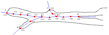
Figure 4: Scheme of the implemented linear interpolation of breaklines without z-values.
In Figure 4 such a situation is shown. The distance of contour line intersection A to the critical nodes K1 and K2 is longer than the distance to the contour line intersections C and B and therefore, the distance to A is taken as base for the linear interpolation.
The input to numerical models for avalanche calculations can be divided into the following three categories:
The one- and two-dimensional numerical simulation models need different kinds of avalanche track specifications. The one-dimensional model requires the specification of the avalanche track-line as well as the width of the avalanche along the track. The track-line has to be defined as a line and the width as polygon coverage. Based on this information and the DEM, the GIS-environment calculates the altitudes along this track profile as well as the width of the avalanche track by determining the closest distance of the track-line vertices to the width polygon arcs on both sides of the track-line.
The two-dimensional model does not require any track or width specification, since the model calculats both elements. Only the calculation domain area has to be specified, i.e. the maximum area that is potentially influenced by the avalanche. The smaller the domain area, the faster the two-dimensional simulation is finished.
For the initial conditions as well as for the flow parameter specification, the GIS-based user interface provides a semi-automatic procedure. A person with avalanche expert knowledge must specify characterising threshold values that are then used by the GIS to classify existing data, such as the DEM or vegetation information. In the following the two different approaches are described. All parameters that have to be specified by the user (avalanche expert) were listed in italic letters.
The criteria that are applied within the semi-automatic procedure to define potential avalanche release areas are based on the following consolidated findings. Generally avalanches can release on slopes between a lower slope boundary (LSB, normally: about 30°) and an upper slope boundary (USB, normally: about 50°) outside densely forested areas. Within this slope range, ridges can divide one single steep slope into many potential release zones, that normally do not release simultaneously. For avalanche hazard mapping purposes, only large avalanches have to be taken into account. Small release areas can therefore be neglected.
To extract potential release areas based on the above-mentioned criteria, a GRID-AML was written. As input, the DEM and a grid containing the forested areas (extract of a digital topographic map with a scale 1:25'000) is used. In a first step, the non-forested areas with a slope angle between LSB and USB were extracted. Within this first step the avalanche expert can also specify whether potential avalanche releases directly above forested areas (RAF) should be considered or not. Since large avalanches normally completely destroy forests in an avalanche track, it can be assumed that slopes above forested areas are not potential release areas of large avalanche events.
In a second step, the size and lengths of these areas were analysed. Areas below a specific minimum area value (MAV) or a minimum release downhill length (MRDL) were eliminated. Whereas it is easy to eliminate the areas within a specific MAV, eliminating areas that do not fulfil the criteria of the MRDL is more difficult: all GRID-cells directly neighbouring the potential release areas were determined (using first the GRID-command "focalsum" with a window-size of 3x3 and afterwards eliminating the values of the potential release areas). Using the GRID-command "flowaccumulation" for each of these release boundary cells the contribution of the above situated area is calculated. When the contribution is less than the value that corresponds to the MRDL, the cell is not considered as a lower boundary cell of a potential release area.
In a third step, the decision is made whether ridges are dividing a potential release zone into two or more single release zones. This decision is governed by a distance threshold value (DTV). This value defines the maximum distance between two neighbouring lower boundary cells. If the distance is greater than the specified DTV, they are considered not to belong to the same potential release area.
In Figures 5 and 6 the release area classification of the same area is shown using two different parameter sets. Table 1 contains the parameter sets that were applied to classify the area.
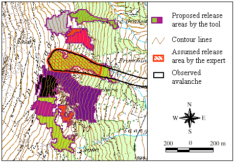
Figure 5: Result of the semi-automatic classification of release areas with a parameter set for extreme avalanche events (see Table 1, column 2).
Digital Elevation Model and Digital Map:© Swiss Federal Office of Topography.
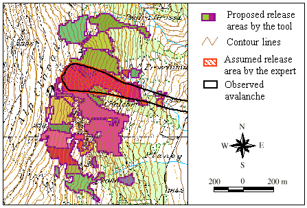
Figure 6: Result of the semi-automatic classification of release areas with a parameter set for mean avalanche events (see Table 1, column 3).
Digital Elevation Model and Digital Map: © Swiss Federal Office of Topography.
| Parameter | Figure 5 | Figure 6 | Lower and upper slope boundary (LSB - USB) | 30° - 50° | 30° - 50° | Minimum area (MAV) | 5000 m2 | 1000 m2 | Minimum release downhill length (MRDL) | 50 m | 50 m | Distance threshold value (DTV) | 20 m | 0 m | Release areas directly above forests (RAF) | no | yes |
|---|
The parameter set applied for Figure 5 is better suited for avalanche hazard mapping, since small release areas are not classified. A comparison of the results shown in Figure 5 and 6 reveals that the DTV parameter has a important influence on the structure of the classified release areas. A distance threshold value of 20 m leads to significantly larger areas than no distance threshold. The comparison of Figure 5 and 6 to a real avalanche event shows, that the semi-automatic release classification was able, with both parameter combinations, to detect the release area of this event sufficiently as one uniform potential release area.
At the moment, this semi-automatic procedure is only a first approach to visualize and classify potential release zones. The avalanche expert has to verify the proposed release areas and to weight them, in order to define the most probable and dangerous release zone that has to be considered for the avalanche hazard mapping. Nevertheless, it is a useful aid in making this important decision. In the section Release Zone Analysis an approach is described that aims to establish a more sophisticated release area classification.
The friction parameters μ and ξ depend on the snow properties, the initial release volume of the avalanche, the vegetation coverage and on the confinement of the topography. GIS is used to define the initial release volume, to vary the snow properties according to the altitude (i.e. it is assumed that in higher regions the snow is generally more loose), to take into account spatially varying vegetation (mainly: forested areas) and to classify the DEM into different areas of confinement. For the latter procedure, the GRID-function "curvature" is used to define the curvature perpendicular to the slope direction. All these spatial classifications were performed so that the friction parameters can be varied along the avalanche track. In Figure 7 an example of an automatically generated assignment for the parameter of the turbulent friction ξ is shown.
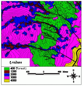
Figure 7: Result of the semi-automatic assignment for the friction parameter ξ based on the topography and the vegetation (forest).
Digital Elevation Model: © Swiss Federal Office of Topography.
Of course, the values for every terrain and vegetation class have to be carefully chosen by an avalanche expert. As for the semi-automatic procedure to delineate the release areas, also within this procedure the avalanche expert has the oppotunity of interactively changing the friction parameter values in areas where he does not agree with the automatic classification procedure.
All the numerical simulation models involved provide various information about flow and deposition depths, velocities and impact pressures. For the purpose of avalanche hazard mapping, the impact pressure is the most important result since the hazard zones are defined by it. GIS allows the visualisation of the pressure forces on maps as well as the combination of results of varying scenarios (i.e. return periods or different release area assumptions) into a combined pressure zone map according to the Swiss Guidelines. This pressure zone map is an important base for the final delineation of the hazard map.
An accurate estimation of the release area is a crucial need for avalanche hazard maps and therefore one of the most delicate problems for the avalanche expert. In order to improve the knowledge about which part or percentage of a whole potential release area will fracture within a specific time period GIS-based research is ongoing.
In the region of Davos, Switzerland, an almost complete database of avalanche events over the last 50 years exists. All perimeters of these avalanches were digitised and can therefore be analysed statistically with GIS-methods. The aim of this study is to derive the main topographic characteristics of the release zones from the DEM and to analyse them in comparison to the real avalanche events. First results show that parameters like "distance to the next ridge", "slope", "confinement" and "aspect in relation to the main wind direction" are well suited to statistically distinguish different frequencies and dimensions of avalanche release areas. In Figure 8 two release areas are shown that have completely different frequencies and main topographic characteristics.
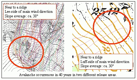
Figure 8: Comparison of the avalanche frequency in two topographically different release areas in Davos. In both release areas the avalanche occurrences of 40 years are shown.
Digital map: © Swiss Federal Office of Topography.
The final goal is to derive general rules and probability distributions for the extent of a release area as a function of the topography and the return periods, that can be applied also to potential release areas where no information of historic avalanche events is available.
Numerical simulation models are still being developed. Often, the more detailed the numerical models are, the more detailed the requirements for the input parameters for the models are. The established GIS-environment has been proved to be a powerful tool to specify all kinds of spatially varying input parameters. It furthermore allows analysing existing historic avalanches statistically and therefore providing additional information to the avalanche expert.
To improve the GIS user interface it is planned to improve the visualisation of the numerical simulation results by creating 3-D perspective views of avalanche tracks with draped ortho-photos or maps as background and to animate the avalanche simulations on these views. This improvement would be very useful for presenting the results of numerical simulation models to an endangered community, in order to increase their understanding of the avalanche hazard on a specific slope.
Bartelt, P., Salm, B. and Gruber U., 1999: Calculating dense-snow avalanche runout using a Voellmy-Fluid model with active/passive longitudinal straining. Journal of Glaciology , Vol. 45, No. 150.
BFF/SLF, 1984: Richtlinien zur Berücksichtigung der Lawinengefahr bei raumwirksamen Tätigkeiten. Bundesamt für Forstwesen (BFF) und Eidg. Inst. für Schnee- und Lawinenforschung (SLF). Eidg. Drucksachen- und Materialzentrale (EDMZ), Bern.
Gruber, U., 1998: Der Einsatz numerischer Simulationsmethoden in der Lawinengefahrenkartierung: Möglichkeiten und Grenzen. Dissertation , Geographisches Institut der Universität Zürich.
Gruber, U., Bartelt, P. and Haefner, H., 1998: Avalanche Hazard Mapping Using Numerical Voellmy-Fluid Models. Publication Nr. 203 , Norwegian Geotechnical Institute, Oslo.
Gruber, U. and Margreth, S., 2001: Winter 1999: A Valuable Test of the Avalanche Hazard Mapping Procedure in Switzerland. Annals of Glaciology No. 32.
Salm, B. Burkard, A. und Gubler, H.U., 1990: Berechnung von Fliesslawinen. Eine Anleitung für den Praktiker mit Beispielen. Mitteilungen des Eidg. Inst. für Schnee- und Lawinenforschung, Nr. 47, Davos.
Swisstopo, 2001: Swiss Federal Office of Topography. Product Information. http://www.swisstopo.ch .
Wood, Joseph, 1996: The Geomorphological Characterisation of Digital Elevation Models. Ph.D. Thesis, Department of Geography of the University of Leicester, Leicester. ( http://www.geog.le.ac.uk/jwo/research/dem_char/thesis ).