A GIS TO TRACE INDUSTRIAL EFFLUENT
- FOR POTABLE WATER RESOURCE PROTECTION
M.C. Swart
Abstract
As a bulk potable water supplier, Rand Water is responsible for the protection of water quality in the rivers. The major problem is to know which industries’ effluent will drain to a specific waste water treatment works (WWTW). To be able to trace these high effluent values at specific WWTW’s to potential industries, there must be a relationship between them.
These connections have been made in ArcView by linking the Industries Database to the Effluent Database, the Drainage Database and the Laboratory Results Database. Potable water resource protection can now be performed optimally.
BACKGROUND
As a bulk potable water supplier, Rand Water is responsible for the protection of water quality in the rivers which drain to the Vaal Dam and Vaal Barrage. This water is not only used for potable water distribution but also for recreation, the aquatic ecosystem, the water environment and for downstream users.
To effectively manage and protect the catchments’ source water, monitoring and proactive decision making are important tasks. Monitoring not only includes the sampling of water at specific sample points and waste water treatment works (WWTW), but also the understanding of the origin of high values of certain variables.
STUDY AREA
Rand Water supplies water to 13 local authorities which supply water to about 9 million people and thus is the main bulk water supplier in the Gauteng area as well as in South Africa.
Figure 1 shows the location of Rand Water’s area of interest in South Africa. The area of interest for Rand Water is the area for which it is responsible, namely the supply and catchment areas located in four provinces. This area is shown in more detail in Figure 2. This map indicates the catchment of the Vaal Dam, the major resource of Rand Water, as well as the Barrage catchment. The latter is the focus of this study in terms of the WWTW located there.
The Barrage is the only catchment area which overlaps with part of the supply area so there is the responsibility of both catchment matters and the distribution of water. The Vaal Barrage is an impoundment of the Vaal River between the Vaal Dam and the Barrage wall. This is a major recreation area in Gauteng. The northern supply area drains north, away from the resource and does not fall within Rand Water’s responsibility.
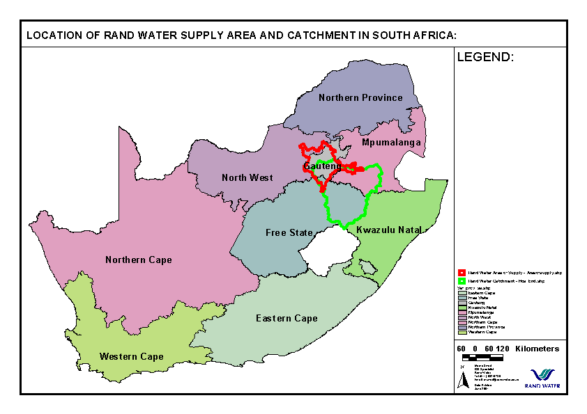
Figure 1:
Location of Rand Water Area of Interest in South Africa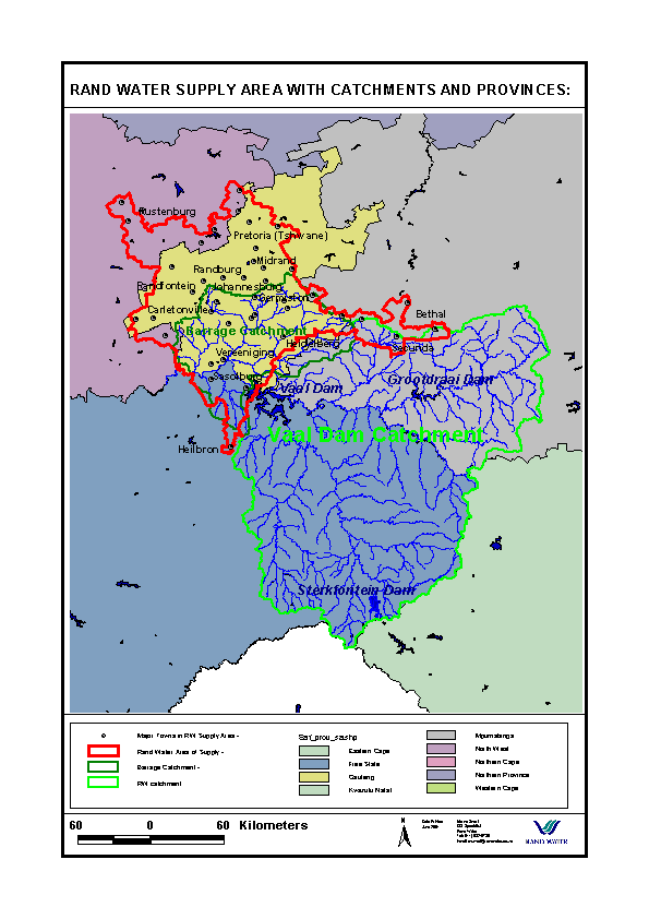
Figure 2:
Rand Water Area of Interest in more detail.
PROBLEM
Number of Industries
In total, the effluent of approximately 13600 industries would potentially drain into the Vaal Barrage. This number includes more than half of all of the estimated 22700 industries in the whole Witwatersrand area, as well as another 1500 industries in the Vaal Triangle and rural areas (Swart, 1999a, b). Therefore, the Vaal Barrage catchment faces a greater potential threat than the Vaal Dam catchment where there are only approximately 1100 industries. Figure 3 indicates the concentration of industries within the area.
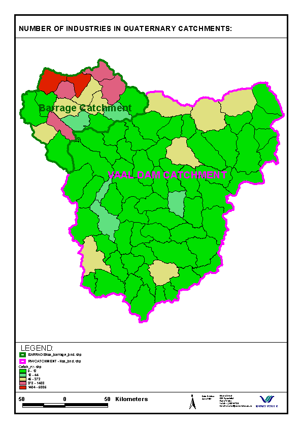
Figure 3:
Number of industries in catchments (Swart, 1999a, b).
Impacted Area
Although this area is not a source of water for potable water purposes for Rand Water at the moment, it is a major recreation area with an important aquatic ecosystem. There is also a responsibility to the down stream users of Parys, Klerksdorp-Orkney, Bloemhof Dam, Vaalharts Scheme and further down stream.
Which Industries ?
The major problem is to know which industries’ effluent will drain to a specific WWTW and sample points in rivers. The Sanitation Section needs to know the origin of specific effluent. Some of the major known problem industries are laundries and dairies. The question now is: Where are these laundries and dairies situated ?
Tracing Specific Variables
The general problems experienced at WWTW could be divided into three types as shown in the graphs in Figure 4. The graphs show the results of the data in the Effluent Database, which contains the variables expected for each type of industry (see Methods, Existing Databases).
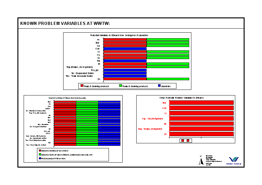
Figure 4:
Known problem variables at WWTW.The major variables that are problematic are BOD, COD, metals, FOG (fat, oils and grease), SOG (soaps, oils and grease) (lower right graph, Figure 4) and detergents (phosphates).
The potential variables in the effluent of laundries and detergent industries (soap and cleaning products) are shown in the top graph of Figure 4.
Three types of industries have been classified as dairy industries, namely:
Their potential effluent is shown in the lower left graph in Figure 4.
The major challenge is to be able to trace the high values of these variables at specific WWTW back to the potential source industries.
AIM
To trace the high values of certain variables at specific WWTW and sample points to the potential source industries.
METHOD
GIS, especially ArcView, is the only method and tool which can be used to solve this kind of problem. To be able to trace the high values of certain variables at specific WWTW to potential source industries, there must be a connection or link between the WWTW, the sample points up and down stream of the WWTW and the source industries.
Existing Spatial Data sets
The existing data sets in shape format with their location shown in Figure 5 are as follows:
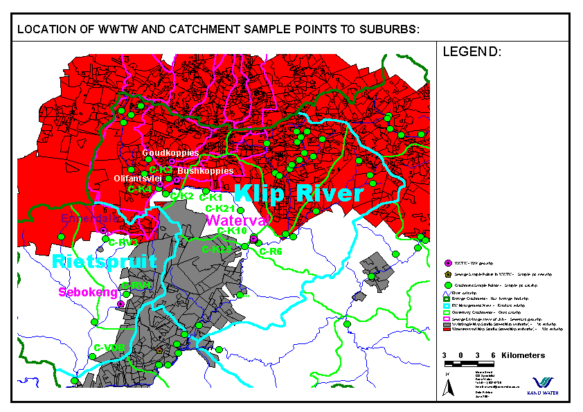
Figure 5:
Location of WWTW and suburbs of Witwatersrand and Vaaltriangle in study area.Existing Databases
The following existing databases were either in Access or developed in Excel and then converted to DBF:
Braby’s Business Database
The part of the Braby’s Business Database that has been purchased from a marketing company has been called the Industries Database because only businesses with a potential effluent to water have been used. It contains the key code [SUBURB_KEY] for the suburb [SUBURB] in which an industry is located, address details and standard industrial codes [SIC] and descriptions. It has been updated from time to time and the new version will be used as soon as it becomes available.
Effluent Database
The variables (chemical elements) which can potentially be found in the effluent of certain types of industries, have been put together into a lookup database (from Water Research Commission reports and other sources). Determining which type of industry will have which type of potential effluent has been the most difficult part. This has been done by a decision classification process of classifying industries into major classes [Major_SIC] according to their SIC and then each major class being divided into minor classes [Minor_SIC] (Swart, 1999a,b). This has then been divided further into smaller classes of more specific type of industries [Indus_Type] (Swart, 1999a, b). From the different sources it can be determined which industry type has which variables as effluent. Next the decision had to be made as to which industry type will represent which SIC in order to be able to bring the SIC to a specific effluent. This whole classification process can be seen in the Effluent Database (Swart, 1999a, b).
Databases developed
Drainage Boundaries and Drainage Database
Using the quaternary river catchment boundaries derived from digital terrain models (DTM) and satellite images, the drainage direction of industrial areas in certain catchments could be determined. From this drainage direction it has been possible to determine the potential WWTW, as well as the sample points up and down stream from it, where the effluent of that catchment could be measured as the drainage areas of sewage generally follow the natural drainage direction.
However, these natural quaternary catchment areas do not represent the actual sewage drainage areas. Sometimes an area is linked to the sewage source in an adjacent catchment by a pumping station. For some areas not even the local authorities know which area is linked to which WWTW. Thus, the sewage drainage areas as used by the local authorities have been compared to the natural quaternary catchments. By using the Geoprocessing Action of Intersect and Clip as well as the Theme on Theme selection, the potential drainage area for each WWTW could be determined.
These potential drainage boundaries have been used to clip out that corresponding area from the Suburb polygons of the Map Studio Street Map data sets of the Witwatersrand and Vaal Triangle (see Figure 6). The suburbs with their key codes are in the attribute table of this clipped suburb data set of each WWTW.
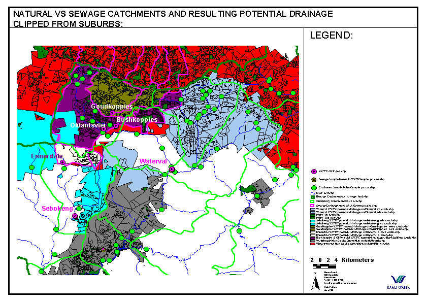
Figure 6:
Natural vs sewage catchments and potential drainage areas clipped from suburbs.Next to each existing record (which includes the suburb name [Suburb] and its key code [Key]), the following fields have been added (see Figure 6):
This field is the name of the works as used in the location data set of the works (Wrk_geo.shp).
Bushkoppies and Olifantsvlei works only have one drainage area because the border between the two is unknown. Therefore for that potential drainage area there are two works [WWTW1] and [WWTW2]. For all the other areas there is only one works namely [WWTW1].
These fields are the names of the sample points exactly as used in the laboratory system LabWare, beginning with a "C-".
These fields are the names of the sample points exactly as used in the laboratory system LabWare, beginning with a "S-".
The value "No_point" indicates there is no sample point or there is no data available.
See the above fields at Table Results (at the end of Results).
All the attribute tables of the suburbs in each WWTW’s potential drainage area, have been combined into one DBF (Drainage_Barrage_wwtw_fn.DBF). In this way a connection has been established between the suburbs in the potential drainage areas of each WWTW and the WWTW itself.
This process has been done for each WWTW in the Klip River and Rietspruit catchments.
Laboratory Data
The laboratory data is in the system LabWare which stores its data in a SQL database. At present a link in terms of hardware and software between ArcView and LabWare does not exist. Data of all measured variables for the period November 1999 to April 2001 for the sewage sample points and upstream and down stream catchment sample points for each WWTW in the Klip River and Rietspruit catchments have been converted from SQL via Excel to DBF. Each sample point’s data set came in separate Excel files with a different order of the field columns. All these Excel files have been combined into one Excel file with the columns in the same order and then saved as a DBF file. This action will be unnecessary if the SDE (Spatial Data Engine) system would be used.
Links between databases
Industries have been located in industrial areas or suburbs by linking their individual data in the Industries Database (with the address details, standard industrial codes (SIC) and descriptions) to the Suburbs Coverage. The relationship between the Suburbs coverage and the sample points and WWTW coverages has been created through the linkage of the Industries Database to the Effluent Database and Drainage Database. The Effluent Database contains the variables (chemical elements and biological indicators) which could potentially be found in the effluent of certain types of industries. The Drainage Database forms the link back to the Sample Point Coverage. The laboratory data (LabWare) of the different water quality variables measured at the sample points and WWTW’s has been linked to the Sample Point and WWTW Coverages. All links have been created in both directions. This relationship between data sets is shown in Figure 6. The layout of the ArcView window with all these linked data sets is shown in Figure 7.
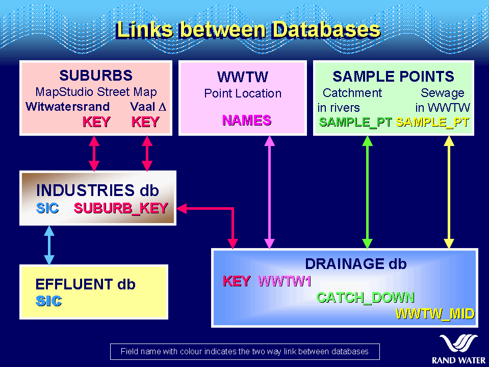
Figure 7:
Links between databases to show relationships.
RESULTS
Many different searches can be done on these linked data sets in the ArcView project. It is best to first do a global search in the whole area and then break the search down to specific areas.
Single Search
Single searches can be done by clicking on the feature on the map or in a database. Clicking on a specific WWTW on the map will show the suburbs of origin of the effluent at that WWTW. The industries records potentially draining to that WWTW will also be highlighted in the Industries Database.
Figure 8 shows an example of the Sebokeng works chosen to show all the areas which drain to it.
Clicking on a suburb on the map or choosing it by using the Query Builder on the suburb theme or on the Industries Database will highlight all the industries located in that suburb.
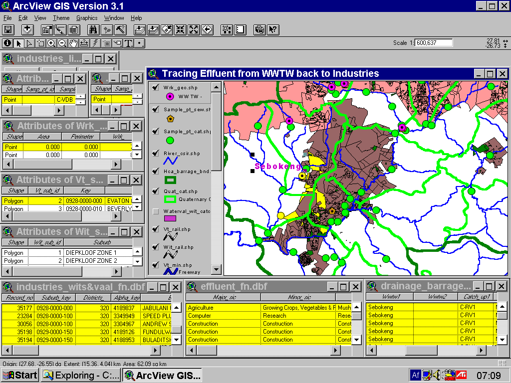
Figure 8:
Single search showing which industries potentially drain to Sebokeng WWTW, with the associated information highlighted in all linked tables.
Specific Searches
An example will now be discussed.
Graphs of variables
Figure 9 and 10 show the results of the laboratory data for Waterval WWTW.
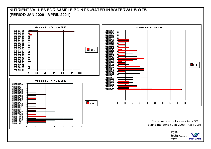
Figure 9:
Values of NH4 (top left), NO3 (right) and PO4 (bottom left) at Waterval WWTW which are potential effluent from dairies.Figure 10:
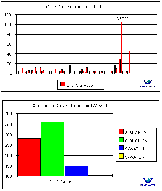
Oils and grease. Top: values for Waterval January 2000 - April 2001. Bottom: Comparison of Oil and Grease values on 12/3/2001 for WWTW's with values - two points at Bushkoppies (S-BUSH_P & S-BUSH_W) and two at Waterval.Nutrients are potential effluent from dairies (Figure 4). Figure 9 shows very high NH4 has been measured on 17/1/200 and very high NO3 on 30/4/2001. When these values for these two dates are compared to all the WWTW, such high values are only experienced at Waterval (graph not shown here).
Oils and grease are also potential effluent from dairies. The graph for Waterval WWTW shows a very high value on 12/3/2001 (Figure 10, top). Use Query Builder on the laboratory database (sample_pt_sew_labdata.dbf) to search for all values on 12/3/2001. The resultant graph (Figure 10, bottom) shows that even higher values have been measured on that day at the points at Bushkoppies WWTW. At the other works no values have been measured or exist and therefore not chosen by Query Builder.
Now the search for the origin of these high values can begin.
Broad area (First search)
Search with Query Builder for dairies in the whole area from Effluent Database.
The result will be highlighted (see Figure 11):
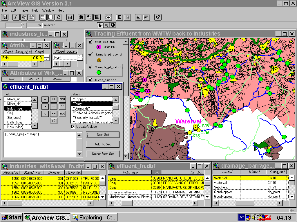
Figure 11:
Broad search for all dairies. Suburb with dairy industries are yellow.
Narrow down (Second search)
Which dairies’ effluent could be expected at Waterval works ?
With Query Builder search for the Waterval WWTW from the Drainage Database but now "sub set" has been chosen.
The result will be highlighted (see Figure 12):
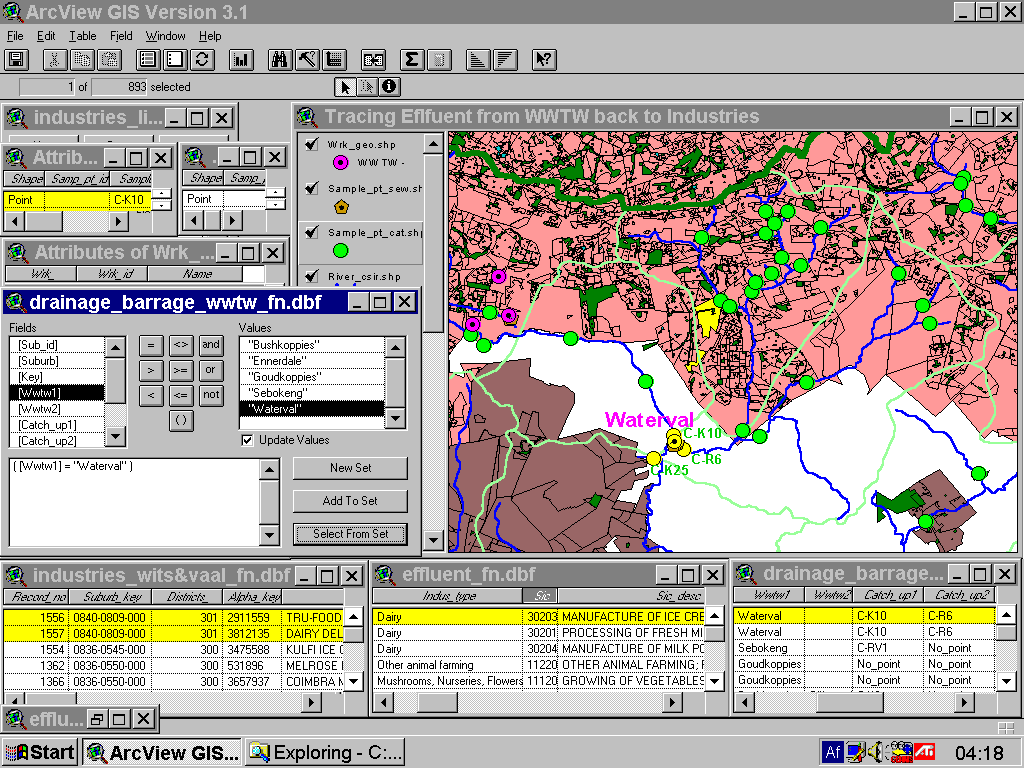
Figure 12:
Narrow search for all dairies in catchment of Waterval WWTW. The suburbs in which they are located are yellow.
Locating street (Third search)
Where exactly are these dairy industries ?
For the location of a specific industry the street could be located in that specific suburb by either selecting the street name from the streets theme or by selecting the suburb in the Query Builder and then clicking the Zoom to Selected button. The view will zoom to that suburb and the streets with their labels will be shown and a map can be printed. Take the two dairy industries in Basalt Road in Alrode making ice cream as examples (See Figure 13).
Industries cannot be linked to their exact street locality because there is no fixed way of giving street numbers in South Africa. Therefore, only a map of a suburb with its streets can be produced. Several projects have been done by different companies to correlate street numbers to specific sections of streets for certain areas. However this method is not accurate and is too expensive. If a street map of a section of a suburb with the address of the potential problem industry has been produced, the investigating officer can easily get to that company.
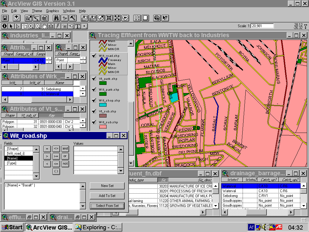
Figure 13:
Locating street of industry. Basalt Street in Alrode (blue feauture) has been chosen using the Query Builder on the streets theme and Zoom to Selected.
Table Results
Details of all the result information in the tables are shown in Figure 14. Highlighted search results in tables showing the industries' contact details (2nd table), then the potential effluent which could be expected from dairies as well as their industrial classification. At the bottom the drainage database showing the suburb with its associated WWTW, catchment sample points and sewage sample points.
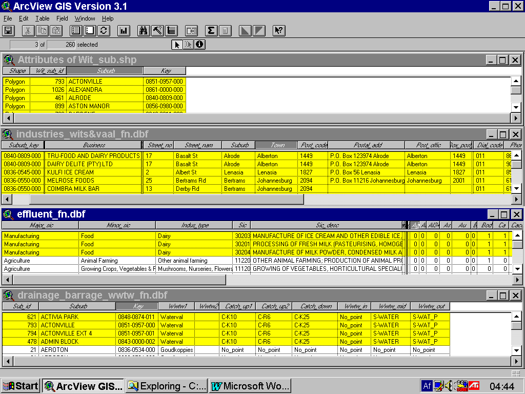
Figure 14:
Highlighted search results in tables.
FUTURE DEVELOPMENTS
A direct link would be established between the laboratory data and the sample points (in WWTW and in rivers) through the usage of SDE. These results would be available to users more regularly, easily and timeously through ArcIMS. In this way decisions for water quality management could be done pro-actively.
In future the census population numbers could be linked to the WWTW as the number of people in an area is an indication of the COD to be expected at that WWTW. If the COD load from households is a given to be expected, everything above that value will have come from industries.
After using the system and clients experience the benefits of it, more needs will develop. As the basic important data sets with the necessary links exist, future expanding and updating will be quite easy. Different kinds of queries are possible because the links exist in multiple tables.
BENEFITS AND CONCLUSIONS
When high values of certain variables occur at a certain sample point or WWTW (according to a graph for that point), it is now possible to:
ACKNOWLEDGEMENTS
REFERENCES
SWART, M.C. 1999:
A GIS Solution For Industrial Problems In Catchments. Paper at: Biennial International Conference of the Society of South African Geographers (SSAG ’99). July 1999, Windhoek, Namibia.SWART, M.C. 1999:
A GIS Solution For Industrial Problems In Catchments. Poster at:: Earth Data Information Systems Conference, co-hosted by SAPGIS (South African Photogrammetry and Geo-information Society) and TAGIS (Transvaal Association of Geographic Information Systems). July 1999, Pretoria, South Africa.
AUTHOR INFORMATION
Marna Swart
GIS Specialist
Water Treatment and Technology,
Rand Water
PO Box 1127
Johannesburg
2000
South Africa
Tel +27 11 682-0736
Fax +27 11 682-0733
E-mail:
mcswart@bigfoot.comRand Water web page:
http://www.randwater.co.zaEsri Users Conference 10 July 2001, San Diego, CA, USA