A wastewater planning project for Nuevo Laredo, Mexico, funded by U.S. EPA, was conducted to rehabilitate sewer collectors and provide for future growth. GIS was used for city-wide utility mapping, various land use analyses, digital elevation modeling, and managing both spatial database sets and physical inspections data.To create a hydraulic model, custom-scripted programs written for ArcView were used to interface spatial information with HYDRA™; HYDRA is a low-cost, effective modeling tool with limited database editing features. This novel approach allows the use of HYDRA; in wastewater planning for projects with extensive datasets, which previously could not be done efficiently.
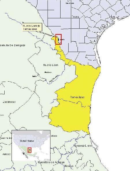
Nuevo Laredo (population over 310,000), Mexico,located on the Rio Grande across from Laredo, Texas (Figure 1), developed into one of the largest international trade ports with the United States after implementation of the North American Free Trade Agreement (NAFTA). Nuevo Laredo, responding to increased economic growth brought on by NAFTA, has experienced annual population growth rates between 2% and 5% for the past several years, and continued high growth is forecasted.
Figure 1 – Location map
High rates of population growth should be countered with equal increases in the coverage and capacity of the wastewater infrastructure.Nuevo Laredo's wastewater infrastructure has not kept pace with the rate of increase in population.This is manifested by the lack of service to expanding urban areas at the edge of the city and insufficient resources to adequately maintain the system in place. As an example, only 88% of the population is connected to sewer service. Where it is in place, the sewer system is undersized and has experienced collapse, leading to overflow during wet or dry weather. These phenomena allow release of untreated wastewater to the environment, and ultimately, the Rio Grande.
This situation is due, in general, to a deteriorating collection system, past engineering practices for short-term fixes, and lack of capital funds for improvements and expansion of the system. These problems are common to border areas experiencing greater than normal population growth. Environmental conditions were so severe in Nuevo Laredo that even before NAFTA programs were enacted, a new wastewater treatment plant and two interceptors were constructed through a cooperative Mexican/U.S. agreement. The project removed 82% of the untreated wastewater discharges, approximately 800 L/s. As a result of NAFTA, a process for obtaining funding for environmental projects was developed to assist communities along the United States-Mexico border.
Parsons was contracted by the International Boundary and Water Commission (IBWC), U.S. Section, to provide Architect-Engineer services for a broad master planning effort to investigate and evaluate the existing wastewater collection system in Nuevo Laredo, plan projects necessary to remove the remaining wastewater discharges, and outline future expansion. The project comprises two phases. The first consisted of field work: data collection, aerial photography, field inspection, flow monitoring, global positioning surveying (GPS) in the field, and base map development. The second phase consisted of diagnosis: physical defects were cataloged, the system was evaluated to identify deficiencies, and a program for implementing corrective measures was proposed. The project culminated in a Diagnosis, Modeling, and Expansion Report for the Wastewater System, which proposed a series of immediate and future expansion projects. The planned projects will remove untreated wastewater discharges to the Rio Grande along the Nuevo Laredo border and prevent reoccurrence of those adverse conditions.
This is a U.S.-funded project to rehabilitate and expand the wastewater collection system with the goal of reducing wastewater discharges to the Rio Grande and improving quality of the environment for Texas and Mexican residents. The project was an inspection, inventory, diagnosis, and evaluation of the components of the wastewater collection system, with primary focus on larger pipes (25 cm or greater). Extensive physicalcharacteristics of the infrastructure components were gathered and numerous system deficiencies were identified. The location of the collection system and critical background information were assigned to coverages (spatial data base layer in GIS, otherwise known as shape files in ArcView) and stored in the GIS; this approach proved efficient because of the smooth transition from the information derived during field studies to the collection system analyses phase The principal coverages included land use, population, and water demands. A digital aerial photograph of the city was produced which served as the basis for the city-wide GIS. All of the above information was utilized to develop the hydraulic model.
The HYDRA hydraulic model was evaluated for dry and wet weather conditions. The existing collection system operates as a combined sewer; and, consequently, existing collectors were modeled with capacity to handle a selected design storm event. Various alternatives were evaluated with the final alternative to be determined by consensus.
The work described herein was performed under oversight and review from a Bi-National Technical Committee (BTC). The BTC is composed of members of Mexican and the U.S. sections of the IBWC, the U.S. EPA, BECC, several Mexican agencies, the North American Development Bank (NADB), consultants, and the municipal utility of Nuevo Laredo. Members of the BTC were involved in all aspects of the study and played a vital role in assuring compatibility of the proposed projects with common operation and maintenance practices in Mexico.
The objectives of this paper are two-fold: 1) to describe the methods and analyses used to perform, evaluate, and assess the system and infrastructure required; and 2) to illustrate the depth of the problems and magnitude of repairs necessary to solve typical problems with wastewater infrastructure encountered in a Mexican border city.
Fundamental concepts utilized to conduct complex system modeling included data integration, automation, and management during the evaluation phase of the project. The main elements are as follows:
This bi-national effort exemplifies the progression of the work accomplished by the City of Nuevo Laredo, and documents the cooperative process, which allowed both the U.S. and Mexico to combine resources in achieving common goals.
This phase includes fieldwork in the wastewater collection and storm water drainage systems. Information gathered was used in the diagnosis phase to construct a model of the wastewater collection and pumping systems. The investigations were critical in identifying the actual condition of the collection system and developing the many coverages.
Field crews obtained and reviewed existing maps, reports, and documentation relating to the water, wastewater, and stormwater drainage systems, as well as COMAPA records of water use, water billing, and industrial wastewater dischargers. This included obtaining records of monthly water use, a digital version of the user registry, appraisal district spatial data, operator interviews, and other historical records.
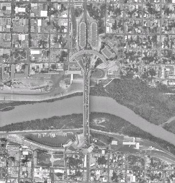
A digital photo of the city, working maps of the water and wastewater systems, and a planning map for the Nuevo Laredo planning area were prepared. The GIS was implemented to manage data and spatial information. The maps were based on existing maps and new information from aerial photography. A digitized aerial photograph of a planning area of approximately 566 square kilometers was prepared under this work element (Figure 2). The photography was used to develop 1:2,500-scale maps at 0.25-meter pixel resolution. A Digital Terrain Model was also prepared with contour intervals at meter. This model was used in Spatial Analyst to generate a triangulated intersection node (TIN) coverage. The coverage was used to delineate drainage basins and aided locating future sewers by way of quickly visualizing optimum routes. 3-D Analyst was used during numerous presentations to illustrate wastewater collections system alternatives to BTC members.
The first phase of flow monitoring quantified overall flows in the wastewater system and began data collection to characterize longer-term flow trends (i.e., seasonal variation in base flows and groundwater infiltration). The purpose of the second phase of flow monitoring was to quantify the flows from selected planning areas upstream of key trunk sewer branches in the wastewater system.
There exist numerous procedures that can be utilized in the field to automate data entry for elements inspected on a terrain. The objective is to locate the item using a GPS instrument while collecting information about the element. However, this does not always prove to be efficient, and the logistics are difficult. Normally, specific crews have particular expertise, and rarely overlap well. Combining them usually decreases productivity. Based on experience on similar projects of this type, a decision was made to operate with separate crews. The first crew would identify and inspect the manholes, recalling that only manholes with primary pipes required inspection. As inspections were conducted, symbols representing the manholes were placed on aerial maps and given an ID. A second crew (GPS surveyors), would use these maps as guides and survey the inspected manholes (i.e., determine the X,Y, Z coordinates with an accuracy of 2.5 cm). Once surveyed, the coordinates of the manholes were updated in the database and avenue scripts used to generate coverages.
Figure 2 – City of Nuevo Laredo Aerial Photograph
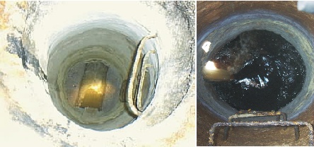
2,700 manholes in the primary wastewater collection system (manholes containing pipe diameters 25 cm or greater) were inspected and surveyed. The inspections recorded such data as construction material; type of manhole cover; diameter of pipes; condition of manhole frame, walls, and base; and any other notable observations such as evidence of infiltration, surcharging or corrosion. Outfalls of wastewater into drainage canals and those stormwater outfalls showing evidence of connection to the wastewater collector system were identified. Approximately 35% of all the manholes in the city were inspected. Several photographs of typical manholes appear in Figure 3.
Figure 3 - Photograph of Surveyed Manholes
Detailed inspection of a pipeline requires closed circuit television which is expensive and time consuming. This technique was not utilized for the study, but rather an association of conditions related to the adjacent manholes was assumed. Pipeline conditions were determined by assigning data links from manholes to pipelines. The procedure,although simple with existing data, is not so trivial with the lack thereof. Since the City actually had no collections system maps with accurate pipeline continuity, the manhole inspections incorporated this task. Pipelines were given a relational ID associated to the upstream and downstream manholes. A depth measurement to all the inlets and outlet was taken during the inspection, and by knowing the surface elevation through GPS, elevations of the pipe inlet and outlet could be determined.
Avenue scripts were used to retrieve the upstream and downstream (X, Y, Z) coordinates from the adjacent manholes. Subtracting the pipe depths allowed the generation of z-polylines to represent the collections system pipelines. Associated manhole defects were aggregated to the pipeline. This required intensive manual data entry and was the most time consuming task of the database development due to the quality assurance needed to make sure manhole IDs were exact as those derived during manhole inspections.
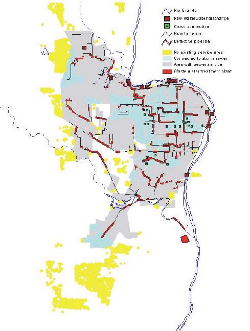
GIS was used to handle data gathered for all the infrastructure elements. This allowed visualization of defect trends;e.g.,numerous wastewater collectors were observed with surcharge and an obvious bottleneck was determined by visualizing locations. Various comparisons were made to relate certain structural deficiencies to overflows or surcharge (e.g., manholes located on dirt roads had the highest percentage of debris). yes"> Figure 4 shows a presentation of the condition of inspected manholes, locations of outfalls, and an approximation of the tributary area of each stormwater cross-connection outfall.
In general, over 60% of the manholes rated in the good operating condition category. A total of 185 L/s of raw wastewater is discharged directly into the Rio Grande due to collapse of major sewers. The worst case are areas that do not have sewer system service and discharge directly to surface waters or drain to stagnant ponds near residential areas.
Numerousdata sets were needed for development and execution of the model. The basic components for planning and analysis for wastewater generation are population projections, population densities, land use areas for 1999 and 2020, and current per capita water use rates.
Figure 4 – Collection System Condition
The City of Nuevo Laredo, as reported by Colegio de la Frontera Norte (COLEF) in 2000, had 310,277 residents, a number expected to grow over the next two decades between 450,000 to 575,000 by 2020, depending on the effects of immigration. The initial population value was adopted from preliminary census data posted by Instituto Nacional de Estadística Geografía e Informática (INEGI) for February 2000. The percent growth was established from a NADB study, which determined a growth rate of 4.59% per year.
The appraisal district developed a land use coverage based on the 1999 aerial photograph produced for this study. The detailed GIS data provide the means of identifying property lots in digital form and allow for convenient analysis and modification. Digital data allowed development of a more realistic population distribution across the City through actual spatial distribution of individual homes. Streets, houses, lots, and significant ground features were identified.
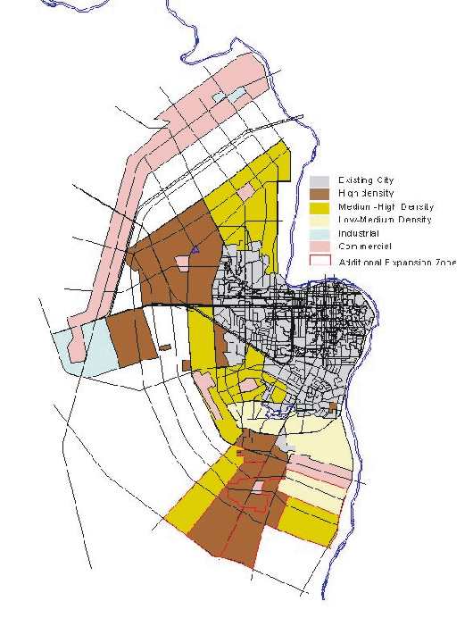
Figure 5 shows existing land use across the City as developed in the GIS database. This existing land use map was agreed upon by the BTC. Information regarding the future land use condition was presented by COLEF and was assumed to be the best available planning information. Additional land use toward the south was identified by COMAPA. The future land use patterns are illustrated in Figure 6.
Figure 5 – Existing Land Use – 1999
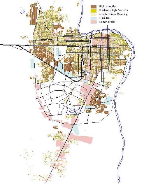
Figure6 – Future Land Use - 2020
Users were classified in the GIS database according to land use type.
The residential demand is somewhat more complex because residential users were derived from two sources:
detailed appraisal GIS data of the existing City, and large scale planning documents of the future area by COLEF.
The residential area was divided differently into sub-categories based on density (people per hectare) by various agencies.
It can be assumed that as population density increases, water use decreases on a per capita basis, because of financial
status. Therefore, the following basic correlation of land use type to water user was made:
The density was calculated in GIS by dividing 4.3 people per household by the area of the house. Once the users were assigned a land use type, they were cross-referenced to their corresponding water demand. Users were then grouped into small sub-drainage basins through a spatial relationship to the delineated drainage basins. These basins were subsequently assigned to nearby pipes of the collection system. This exercise is called spatial water demand allocation (i.e., application of water demands based on a type of land use to the pipe network). A similar calculation was made for industrial users and commercial service based on area rather than population.
Current water demands and wastewater generation can be estimated based on existing COMAPA records. The principal set of records for COMAPA is a FoxPro database that consists of historical water consumption values for each user. A user is defined as a single connection (e.g. a household, business, etc.). The reports were summarized and adjusted based on actual field flow measurements. The actual water demand adjustment was complex and is beyond the topic of discussion for this paper, furthermore, these calculations were not dependent on GIS or modeling.
In summary, water usage rate is measured in liters/capita/day (L/cap/d) and was calculated by dividing the adjusted water demand for each subcategory by the population. The wastewater generation factor was calculated to be 75% of the water demand
Programs to promote water conservation over the next several years are considered critical in this region of Mexico. COMAPA is currently constructing projects to improve some efficiency of the system. Programs to improve meter accuracy, increase percent return of billing, develop penalties for excessive water use, implement reclaimed water use, and minimize waste have been developed from other studies and are in the process of being implemented.
GIS programming, data links, and data automation procedures allowed for convenient and efficient transition from system data (collection system layout, land use, and service areas) to hydraulic modeling.
Design criteria and modeling assumptions for the wastewater systems were developed using both U.S. and Mexican standards, generally as presented in relevant guidance documents from U.S. EPA and Comisión Nacional de Agua (CNA). Values were discussed at length and coordinated with the BTC to assure both U.S. and Mexican standards were realistically achievable. Main criteria used for the hydraulic model are presented in Table 1.
Table 1
Collection System Modeling Criteria
|
Item |
Value |
| Pipe Material | Concrete, Ductile iron, HPDE, PVC |
Design Slopes |
0.0004 – 0.0025 per CNA guidelines |
Manning’s Coefficient |
Concrete=0.013, HDPE=0.011, PVC=0.011 |
Minimum Flow Velocities |
0.60 m/s |
Flow depth at average flow |
80 percent of diameter |
Flow depth at peak flow |
Allow surcharge up to 0.5 m freeboard at the lowest manhole. |
Minimum depth of cover |
90 cm |
Infiltration rate |
Considered as part of per-connection flow |
| Inflow |
Modeled as a combined sewer, with inflow of runoff assigned to each manhole. |
The HYDRA model assigns flows to pipes using information for land use and accumulates flows through a service basin with a single injection point within the basin. The flow is distributed according to the diurnal curves determined from flow monitoring and is the principal component used to calculate the peaking factor of the basin. These flows are modeled using a time step series calculation utilizing complex hydraulic algorithms that simulate water flow in pipelines. The software is quite capable of doing the analysis; however, the entry of data for various elements most often results in the most time consuming and expensive effort of modeling.
Data in the field was managed using GIS by way of ArcView files know as shape files. HYDRA utilizes a simple ASCII text format for its graphical representation of model components as well as a very accessible database for the graphics. Care was taken from the onset to assure that the nomenclature required within HYDRA was utilized within the GIS (e.g.,pipe IDs could only be numeric). Avenue scripts were used to export coordinates of the manholes, pipelines, and basins into the exact text format used by HYDRA. Upon initial opening in HYDRA, a database file was created for the particular element, otherwise noted as a DBF file. ArcView had the capability of accessing this file concurrently while HYDRA was running. The shape files were then linked to the HYDRA database, which allowed easy transfer and manipulation of the characteristics of the elements. The database link was assured since the shape files themselves generated the HYDRA graphic files. This proved to be very powerful during editing and the generation of new models.
Drainage basins in the model required the number of habitants and commercial/industrial users, their water consumption, and types of flow response. This information was managed in the GIS by way of the land use maps. The drainage basins information was determined through a land use intersection with the delineated basins. Values were proportioned according to area.
The most difficult task was quality assurance on the pipeline coverage. The most common data gaps and the avenue scripts used to resolve them as well as other data manipulations are listed below:
Design flow parameters were based on flow monitoring data collected and other pertinent information. These parameters included unit flow rates, storm water inflow, and the design storm event. As mentioned the wastewater collection system for Nuevo Laredo is a partially combined system. While few direct connections from public storm drain appurtenances are connected to the wastewater collection system, the presence of private yard drains connected to the collection system do produce some combined sewer characteristics.
To calculate peak runoff flow rates, a run-off coefficient (C) value must be assigned to each basin. The appraisal database was utilized to assign the C values on an area basis according to land use type. The C value for each lot was applied in the GIS, and the overall average was determined for each drainage basin. This is a computation that could not have been reasonably done using a non-spatial database.
HYDRA has relatively no graphing capabilities, i.e., the software does not enable map production of its result outputs. However, the model does produce an ASCII output file. The file could be imported into ArcView and linked to the original shape file; a capability that allowed development of desired maps for inclusion into deliverables or for presentations. The link also allowed for quick visual interpretation of modeling results during the evaluation process.
Once the model was calibrated, alternatives were evaluated using established design criteria. Alternatives for the new collection system were based on the road system layout adopted by City planning, a terrain map developed by Parsons using the digitized elevation contours, and two collection system strategies agreed upon by the BTC during previous workshops. Almost all of the alternatives under consideration reflected varying strategies for the number and locations of wastewater treatment plants, and for placement of the collection systems that would be required to deliver the wastewater. Location of the final discharge point defined the effluent quality requirements. Because treatment costs are directly related to the effluent water quality produced, collection system costs are directly related to location of the downstream end of the collection system.
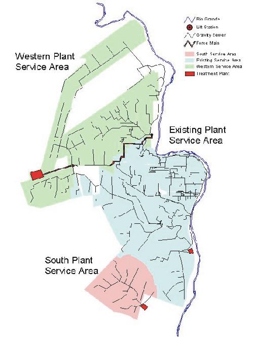
Each alternative layout was evaluated based on preliminary cost estimates as well as benefits and disadvantages associated with each layout. The final layout consisted of a new treatment plant serving the northwestern part of the city, the existing plant serving the central section, and a new plant serving the Las Animas basin. It includes a wastewater treatment plant far from the City, and provides treated water near high re-use areas. When water reuse is not needed it can be discharged to an arroyo that is far removed from the intakes of the Laredo and Nuevo Laredo potable water treatment plants. The BTC selected an alternative that minimized operational cost, had the highest water reuse potential, and did not discharge upstream of the potable water treatment plants. Figure 7 presents the selected alternative.
Figure7 – Proposed Future Wastewater Collection System
Based on results of the hydraulic modeling, a system of improvements was developed. This system consists of two types of projects: Rehabilitation and Expansion. Rehabilitation projects focus on restoring or improving service to areas that have existing, but insufficient, wastewater infrastructure or to increase coverage to areas lacking service. Expansion projects are intended to serve residents in projected growth areas. A crucial element of the rehabilitation project was to remove raw wastewater discharges into the Rio Grande and reach 100% coverage of the wastewater system. In conjunction with this, the projects developed are intended to be compatible with infrastructure planned for the future. The rehabilitation projects included fixing cross-connections or counter slopes that cause surcharge as well as provide service to areas with no sewers. The majority of the deficiencies in the existing basin were due to pipes that were collapsed, flat, or counter-sloped. Several of the service areas toward the outskirts of the City required new collectors.
Nuevo Laredo is expected to grow significantly in the future with the majority of the growth along the river and central parts of town. The first phase of constructing the future basin system will be to build a wastewater treatment plant west of the City. The basins are designed to follow along natural waterways whenever possible. All the future collectors located north and northwest of the City will be directed to this treatment plant. In combination with the treatment plant, two lift stations will be needed to direct the wastewater flow to the new treatment plant.
Capital cost data for the rehabilitation and expansion projects and annual operation and maintenance costs for the entire wastewater collection system are presented. Table 2 shows the final cost summary for all the projects. System improvements will require $3.5 million dollars for immediate rehabilitation projects. Future capital improvement projects require an investment of $37.3 million dollars over the next 20 years. Accounting for a population ranging from 310,000 to over 700,000, this investment roughly equates to nearly $50 per person per year. This cost may not be reasonably absorbed by the citizens. This clearly identifies the need for external funding to aid in construction of these projects.
Table 2 – Final construction cost summary
|
Project |
Capital Cost |
| Rehabilitation Project | |
| Gravity sewer | 3,500,000 |
| Cleaning | 500,000 |
| Total | 3,500,000 |
| Expansion Projects | |
| Gravity sewers | 27,000,000 |
| Diversion structures | 120,000 |
| Lift stations | 4,500,000 |
| Force Mains | 5,700,000 |
| Total | 37,320,000 |
Some of the conclusions derived from this 2-year long project include the following:
Marcel Dulay,P.E.
Parsons
8000 Centre Park Drive, Suite 200
Austin,TX 78754
Phone:(512)415-3144
fax:(512)719-6099
Marcel.P.Dulay@Parsons.com