Edward Copeland,
Senior GIS Specialist
Turner Collie & Braden Inc. (TC&B)
Austin, Texas
Brian McCaig,
Graduate Engineer
Turner Collie & Braden Inc. (TC&B)
Austin, Texas
The Clearwater Underground Water Conservation District contracted with Turner Collie & Braden Inc. to develop tools that can be used to monitor groundwater resources, evaluate data, and assist in the development and implementation of the District's groundwater management through the creation of thematic maps and three-dimensional (3-D) aquifer models within ArcView Geographical Information Systems (GIS). This paper describes how this was achieved through the integrative approach of creating a groundwater database and graphical user interface that links Microsoft Access and ArcView with the Spatial Analyst extension, which will permit the District to evaluate historic water well and hydrogeological data as well as collect and evaluate new data. This case study can also serve as an example of how the use of GIS can benefit other groundwater conservation districts throughout Texas and across the nation in managing the groundwater resources within their jurisdictions.
In 1949, the legislature of Texas passed the provisions for the creation of locally managed groundwater conservation districts to conserve, preserve, protect, and recharge the groundwater resources of the state. Groundwater conservation districts are charged with six management objectives under the Texas Administrative Code. These objectives include: efficient use of groundwater within a district; minimization of groundwater waste; development of a contingency plan to mitigate water-level declines during periods of drought; development of public and private partnerships; control and prevention of land surface subsidence as a result of groundwater withdrawals; and, identification of natural resource management issues relating to endangered species and/or water quality. Each groundwater conservation district is able to establish individual performance standards to meet the management goals dictated by Texas law. GIS can prove to be a valuable tool in establishing and assisting the groundwater conservation districts with their performance standards since it permits data to be geographically referenced and can be used to create static groundwater models. This paper discusses how GIS and Microsoft Access were linked together to perform necessary groundwater management tasks for the Clearwater Underground Water Conservation District (CUWCD) in Central Texas, can also be useful to other groundwater conservation districts, as an example of how to effectively meet their management needs.
In 1989, the Clearwater Underground
Water Conservation District was created by the 71st State Legislature and was
confirmed by the voters of Bell County in August 1999. The District's jurisdiction
includes the portions of the Edwards Balcones Fault Zone, Hensell and Hosston
aquifers within the boundaries of Bell County, which is located about 50 miles
north of the City of Austin in Central Texas.
The District's goal is to "develop and implement an efficient, economical, and environmentally sound groundwater management program to protect and enhance the water resources of the District." In order to meet the objectives set forth by the legislation creating the groundwater conservation districts and its mission statement, the CUWCD contracted with Turner Collie and Braden Inc. to assist them with two primary tasks: 1) a comprehensive analysis of the hydrogeological processes of the three aquifers, and 2) an examination of the interaction of the aquifers with the municipal, industrial, and agricultural sectors of the local economy. These processes were evaluated in order to develop tools, which will enable the CUWCD create and enforce their performance standards.
The CUWCD identified four of the
six management goals listed in the Texas Administrative Code as being relevant
to the aquifers in their jurisdiction - presently, land surface subsidence and
impacts to endangered species and water quality are not problems within the
District. However, the first four goals listed above are of primary importance
to District, and the following preliminary performance standards have been established
for each of these goals:
STUDY SITE DESCRIPTION
Determining the geology and groundwater characteristics of the District's jurisdictional area (study site) is essential because the structure of the aquifers will dictate how GIS should be used as a management tool. Aquifers are classified as either water table or artesian aquifers. The quantity of available groundwater in a water table aquifer is determined by the specific capacity of the water-bearing formations, the thickness of the aquifer, and current water-level measurements. GIS can easily determine the quantity of available groundwater in a water table aquifer if the specific capacity is known (or can be reasonably estimated from the lithology of the formations) and well logs and water-level measurements are available for the water wells in the study site. Furthermore, GIS can make estimations of the specific yield for a water table aquifer after records of water discharge from the aquifer and the subsequent decline in the water table are measured over a period of time. Determination of available groundwater in artesian aquifers is more complicated, in that the quantity of water also depends on the confining (pressurized) characteristics of the aquifer. For a confining aquifer, the properties of the water-bearing formations and the confining characteristics are described by the storativity of the aquifer, which is more difficult to calculate than specific yield since it changes as the pressure within the aquifer changes as water is removed from or added to the aquifer. Consequently, determination of available groundwater volumes in GIS should be conducted in a different manner for an artesian aquifer than for a water table aquifer. Similarly, estimations of potential recharge to an aquifer should be analyzed differently with GIS depending upon the aquifer classification. Ordinarily, water table aquifers should have higher recharge potential than artesian aquifers, which generally do not contain water-bearing formation outcrops. An exception to this rule would be when there are faults or porous confining layers that can provide substantial volumes of groundwater recharge to an artesian aquifer. Differences in groundwater availability and potential recharge locations are only a couple the ways that the geology of a study site impacts how GIS should be used as a management tool. The rest of this section describes the geology specific to Bell County.
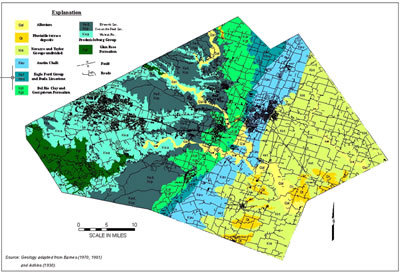
The study site currently encompasses the entirety of Bell County, Texas and includes three aquifers: the Edwards Balcones Fault Zone (BFZ), the Hensell, and the Hosston aquifers. The Edwards BFZ aquifer consists of formations such as the Georgetown, Edwards, and Comanche Peak that outcrop in the central part of the County. These formations are downthrown toward the southeast giving the Edwards characteristics of both a water table aquifer and an artesian aquifer. The other two aquifers, the Hensell and Hosston, are both located in the Trinity geologic group and are collectively referred to as the Trinity aquifer. The Trinity aquifer is separated from the Edwards (BFZ) by the highly impermeable Glen Rose formation, which outcrops in the western part of Bell County. Consequently, these two aquifers are characteristic of artesian aquifers. Figure 1 below depicts the study area and surface geology that occurs within the District and illustrates the locations of the outcrop formations of the Edwards (BFZ) aquifer and the Glen Rose formation in the central and western portions of the County.
The conditions under which the aquifers exist dictate the quantity and quality of available groundwater for industrial, municipal, and/or agricultural uses. Depending upon the geologic structure of the aquifer, groundwater availability is determined either by the storativity or the specific yield of an aquifer. The storativity of an artesian aquifer represents the volume of water released from storage due to expansion of water or compaction of the aquifer when there is a change in pressure. This may be contrasted with the specific yield of a water table aquifer, which represents the actual volume drained from an aquifer. Consequently, assuming the entire Edwards BFZ aquifer to be a water table aquifer, the volume of the available groundwater in Bell County at the time of this study ranges from 50,700 to 101,400 acre-feet.
(Click image to view full scale)
Figure
1. Surface Geology Map of Bell County, Texas
Source: LBG-Guyton and Associates.
This range represents the volume of groundwater stored in the aquifer that is
currently accessible for use by pumping. The Edwards BFZ aquifer's total water
storage capability is much larger and is estimated to be 1.5 to 4 times the
available volume. For the Hensell and Hosston aquifers combined, the volume
of available groundwater at the time of the study was estimated to be 44,500
acre-feet and the total storage capability is estimated to be around 32 million
acre-feet. The total storage capability of these two aquifers is so much greater
than that for the Edwards BFZ because the Hensell and Hosston are confined aquifers
where the water has been stored under pressure. Therefore, the District currently
has an estimated combined total between 95,200 and 145,900 acre-feet of available
groundwater resources that need to be effectively managed.
The Balcones Fault Zone is a narrow
geologic area that spans the state from the Rio Grande to the Red River and
consists of broken rock formations, or faults. This fault zone extends north-northeastward
through the central part of Bell County. This faulting has displaced the geologic
formations within the County causing the older geologic formations to outcrop
in the western portion of the County and the younger geologic formations to
erode and deposit in the topographically lower elevations in eastern Bell County.
This fault zone is also responsible for the discontinuities of the three aquifers
as they extend southeastward and it is these discontinuities that provide the
dual characteristics of the Edwards (BFZ) aquifer and control the flow of groundwater
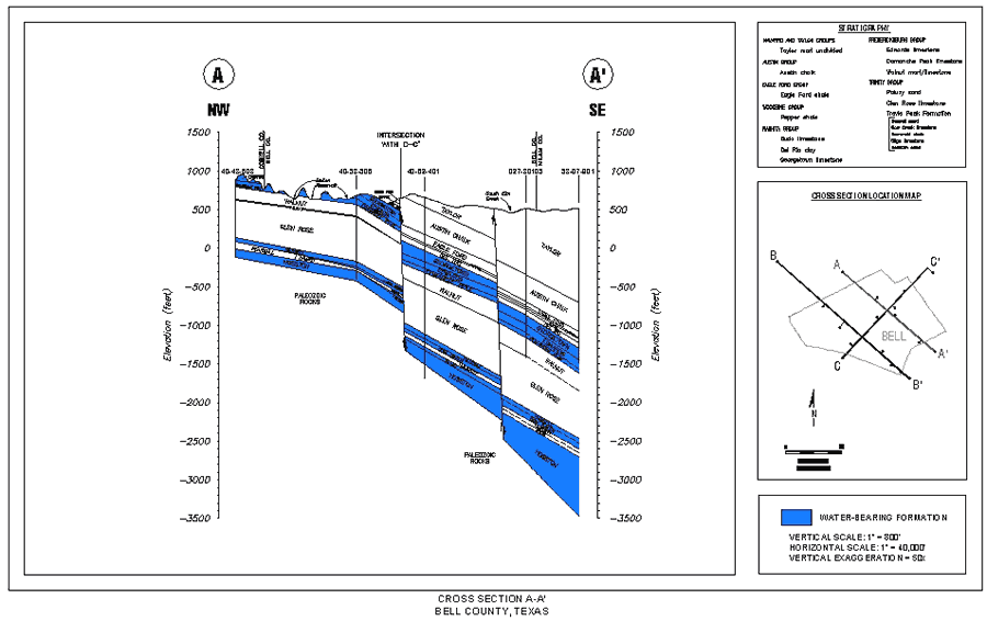
in all three aquifers throughout the County. Figure 2 below is
a geologic cross-section (A-A') extending northwest to southeast through Bell
County illustrating the discontinuities of the water-bearing formations of all
three aquifers.
Figure
2. Geologic Cross-Section (A-A') extending northwest to southeast across Bell
County illustrating the vertical displacement of the aquifers due to the extensive
faulting characteristic of the Balcones Fault Zone. Source: LBG-Guyton and Associates.
The following section of this report describes the steps taken by TC&B to develop management tools for the CUWCD and how these tools will be used to effectively establish and maintain the District's performance standards.
A variety of tools were created for the Clearwater Underground Water Conservation District to assist in the establishment and maintenance of their performance standards and management goals. These management tools include the creation of thematic maps in GIS with a link to Microsoft Access, which permits the District to store and organize their existing data, as well as to update their records as new data becomes available or new wells are permitted; and, update the static groundwater models created with the thematic maps and three-dimensional analyst. The following sections describe how the thematic maps were created and their importance in managing the aquifers as well as how the Microsoft Access database operates and links to ArcView GIS and how a three-dimensional static model of the aquifers was created using ArcView's 3-D Analyst extension.
1 TIGER - Topologically Integrated Geographic Encoding and Reference System
2 SSURGO - Soil Survey Geographic
The first step in managing the groundwater resources of the CUWCD is to identify the wells within its jurisdiction. Well records were acquired in both a GIS format and in a tabular format with latitude and longitude coordinates. Incorporating these wells with base map data allows the District to visually locate all the wells within its jurisdiction, which enhances their analyses of well monitoring data such as water levels, water quality, and well yields. In addition, since the database also contains information regarding the well depth, aquifer code, well type, water use, and available logs, the District can instantly identify many well parameters throughout the County. Figure 3 below is a sample of the potential themes available and illustrates the location of each water well in Bell County and surrounding counties, its depth, and the aquifer in which it is located.
(Click image to view full scale)
Figure
3. GIS Thematic Map illustrating the location, aquifer identification, and depth
of each water well within Bell County and surrounding counties.
Source: Texas Water Development Board.
Next, the topography of the Bell County was created using United States Geological
Survey (USGS) Digital Elevation Map (DEM) data. Topography data is required
to calculate an aquifer's physical thickness as well as its historic saturated
thickness. The topography data also indicates the general direction of groundwater
flow from the high limestone and sandstone hills in the western part of the
Bell County reaching 1,200 feet above mean sea level (msl) to the coastal plain
sediments in the eastern part of the County at about 400 feet msl.
The thickness for each of the three aquifers was developed from driller's logs identified in the well records from the TWDB, TNRCC, and BEG. The geologic formations were identified from the logs and their depths were entered into a database. This data table was joined by the state well identification number to the well data shapefile, which were converted into two grid themes: one grid theme representing the depth to the top of the aquifer and the other representing the depth to the aquifer bottom. Next, the elevations of the top and bottom of each aquifer was determined by subtracting these grids from the USGS DEM. Finally, the aquifer thickness was calculated by subtracting the bottom elevation of the aquifers from the top elevations. Figure 4 illustrates the aquifer thickness of the Edwards (BFZ) aquifer.
(Click image to view full scale)
Figure
4. Thematic Map illustrating the thickness of the Edwards (BFZ) aquifer in Bell
County.
Source: LBG-Guyton and Associates.
The total storage of volume of the Edwards (BFZ) aquifer was determined based
upon the specific capacity of the aquifer and the aquifer thickness. This assists
the District with its management goals because expected trends in fluctuation
of groundwater volumes can be determined for a range of drought conditions.
As water-level measurements are gathered, groundwater elevations can be calculated
and the saturated thickness of the aquifer can be estimated and compared to
the total storage of the aquifer and estimations of saturated thickness for
other time periods. Consequently, the District can determine how the aquifer
reacts to drought conditions or responds to recharge.
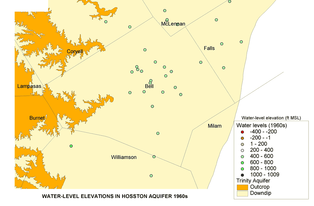
Well record data from the TWDB and the TNRCC contains historic water level measurements for all three aquifers. This data can be grouped for a range of years to show water level trends for that time period. For the CUWCD, water level measurement data was grouped by decade to show water level trends from 1950 to 2000. Figure 5 below illustrates the water level measurement coverages created in ArcView for the Hosston aquifer wells in the 1960s and 1980s, respectively. These figures illustrate that the water levels in the Hosston aquifer have been decreasing through the period of record indicating that the groundwater is being mined from the aquifer.
Estimation of potential existing recharge and determination of areas that could be used to enhance recharge artificially is a vital aspect of groundwater management for the District, because this recharge information combined with data on the amount of water discharging from the aquifers is used to calculate a groundwater balance. Locating areas of potential recharge is based upon the geology of the study area, climate data such as precipitation and evapotranspiration, soil types, and location of physiognomic regions. The geologic map locates the outcrop areas of the aquifers where recharge potential is highest. The precipitation theme identifies the average annual precipitation of the study area relative to the outcrop areas of the aquifers. The physiognomic region and evapotranspiration themes identify the average annual water loss in the Bell County due to evaporation and transpiration. The soil type theme identifies areas of high and low infiltration rates.
p07105b.gif" width="1024" height="671">
Figure
5. Thematic Map created to illustrate Hosston aquifer water level elevations
in the 1960s as compared to water elevation measurements taken in the 1980s
-1990s.
Data Source: Texas Water Development Board.
In order to create a potential recharge map, the themes described above were converted from Esri shapefiles to grid themes in which each cell was assigned a value relative to its recharge potential. Afterward, the grid themes were combined together, and the summed values of the cells grouped together into categories of "low recharge potential", "medium recharge potential", and "high recharge potential". Figure 6 illustrates the potential recharge map of the Edwards (BFZ) aquifer developed for the CUWCD.
(Click image to view full scale)
Figure 6. Thematic Map illustrating the potential recharge areas within Bell County.
A database was created in Microsoft Access containing all the information available in the well records. Such information includes the well and driller information, available logs, water-level measurements, pump and casing data, and well location as previously discussed. Also, in expectation of future study and analysis, additional areas of data input were created for water quality, water pumping, well equipment, and detailed casing information. The creation of this database permits the District to immediately update their well information and create new thematic maps that reveal the changes in the groundwater availability in these three aquifers.
Another benefit of the database is its simplicity and convenience. By creating Adobe Acrobat PDF files, the District can permit new or existing well owners, to update their well information remotely, and to update the database files instantly. Also, reports can easily be generated for all or part of the wells in Bell County that incorporate various aspects of the well records.
The information in the database is easily navigated by a program operator through the use of a graphical user interface (GUI). The GUI is a series of user forms that requests information from the user, which allows them to proceed through the hierarchical structure of the database. For example, the user can proceed through the database via the GUI to enter information for a new well; to edit information for an existing well including new data such as recent water level or water quality measurements; and/or to perform a query search for a particular well or well owner information. Figure 7 below illustrates the hierarchical structure of the database created for the CUWCD.
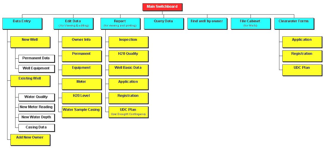
Figure 7. Structure of the Microsoft Access database created for the CUWCD.
The GUI is focused around the Main Switchboard illustrated in Figure 8
below. From the Main Switchboard, a well user can either enter data for a new
well by selecting "Data Entry"; enter data for an existing well by
selecting "Edit Data"; create a report by selecting "Report";
or, perform a query by selecting either "Query Data", "Find Well
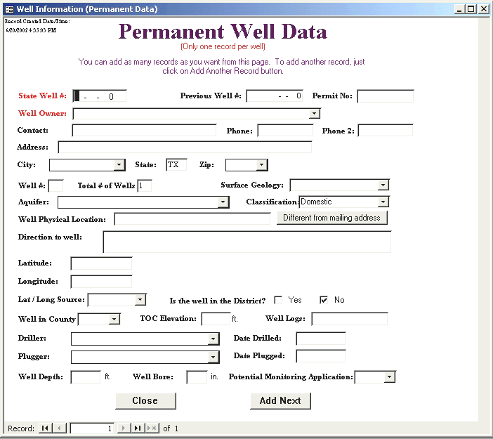
by Owner", or "File Cabinet for Wells". Types of new well information
includes state well numbers, well location, well owner, well driller and date
drilled, the well depth and bore, and the well's surface geology. Other information
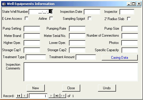
that can be entered for a new well includes well equipment data such as pump
size, pumping rate, pump setting, and storage capacity. Figures 9 and 10 subsequently
illustrate the GUI forms for new well data input created for the CUWCD.
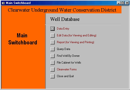
Figure 8. Main Switchboard GUI illustrating data input options into Microsoft Access.
Figure
9. GUI Form illustrating permanent well data input for new permitted wells.
Source: Adapted from database created by the Barton Springs Edwards Aquifer
Conservation District.
Figure
10. GUI Form illustrating well equipment data input for new permitted wells.
Source: Adapted from database created by the Barton
Springs Edwards Aquifer Conservation District.
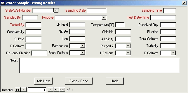
Types of existing well data includes water quality, water metering, well casing, and water depth information. Examples of the GUI forms created for existing well data input for the CUWCD are illustrated in Figures 11 and 12. The report option allows the user to create reports based upon multiple criteria. For the CUWCD, six report criteria options were created that include inspection reports based upon water metering information; water quality reports; basic information reports based on state well number and well owner; well application forms; well registration forms; and, user drought contingency plans. Figure 13 is an example of the well application form created for the CUWCD. The final user option is performing queries based upon particular information. Queries can be performed from the three options on the Main Switchboard. Since all the information entered into the database is linked to the unique state well numbers, any search criteria input into the GUI query forms is linked to all the wells within the District. An example of one of the GUI query forms created for the CUWCD is illustrated in Figure 14.
Figure
11. GUI Form illustrating water quality testing data input for existing water
wells.
Source: Adapted from database created by the Barton Springs Edwards Aquifer
Conservation District.
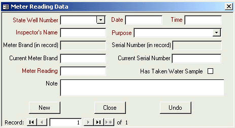
Figure
12. GUI Form illustrating water meter data input for existing water wells.
Source: Adapted from database created by the Barton Springs Edwards Aquifer
Conservation District.
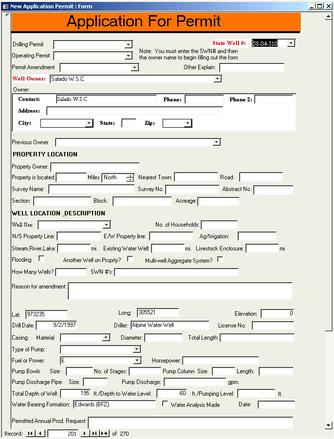
Figure 13. Permit Application GUI form created for the CUWCD.
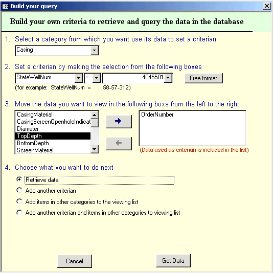
Figure 14. Query GUI form created for the CUWCD.
Similar databases that organize data according to a district's respective rules can be created for other groundwater conservation districts. Some groundwater conservation districts may not have the capability or the jurisdiction to consistently monitor water quality or water pumping rates, for instance. Other districts, however, may employ more stringent monitoring programs. The benefit of the database is its ability to organize, update and secure data regarding well ownership, well mechanics, water pumping, and aquifer properties to the extent desired by the particular groundwater conservation district.
While the information on the wells can be easily viewed from within Microsoft Access, it is also very desirable to be able to see the same sort of information from ArcView by pointing the mouse cursor on a well location and clicking on it to "query" and view the information contained in the Access database for that specific well. This type of capability is possible in ArcView through an Open Data Base Connectivity (ODBC).
For an experienced ArcView user, the process of connecting to the Access database and joining it to the Well shapefile is a fairly straightforward task; however, without the proper training this can be difficult and confusing to achieve. In order to eliminate the need for this type of training, as well as to speed up the process, it was determined that an ArcView extension should be created to connect to the Access database and to join it to the Well shapefile.
An initial review was conducted on the database to identify the type of data that would most likely need to be accessed within ArcView. Three types of data were identified: well owner data; well permanent data; and, water quality data. In Microsoft Access three queries were created for this data. Each query also included the field containing the State Well Number as a common identifier.
An ArcView ODBC extension was developed for the CUWCD that would automatically connect to the Access data using these three queries and to join the data to the Well shapefile using the common identifier. To simplify this process, the extension will "load" buttons on the Button Bar of the View document. Clicking on the "Well Owner Data" button allows the extension to connect to the well owner data in the access table and will join it to the Well shapefile. Press on the button for the well permanent data, and likewise this data will be joined to the Well shapefile.
A three-dimensional model of the aquifer was created for the CUWCD from the Esri shapefiles created from the grid themes of the top and bottom aquifer depths previously discussed. Each shapefile was converted to a triangulated irregular network (TIN) file and displayed into ArcView's 3-D scene feature based on the attributes of the shapefile from which they originated. The fill effects of the aquifers were created into an Esri shapefile using a script file created by John Grayson. The locations of the wells within the 3-D model were created based up the well log information input into tabular data format. Figure 15 illustrates the 3-D model of the Edwards (BFZ), Hosston, and Hensell aquifers that were created for the CUWCD.
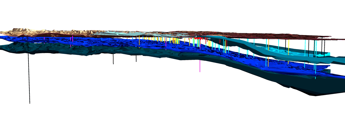
Figure 15. Example of the 3-D groundwater model for the Edwards (BFZ), Hensell, and Hosston aquifers that are under the jurisdiction of the CUWCD.
The development of public and private partnerships through outreach and educational
programs is the reason the three-dimensional model is useful to groundwater
conservation districts. The model permits both public and private entities to
visually interpret impacts to the aquifers caused by drought and anthropogenic
uses.
The GIS and Microsoft Access database are the ideal tools to assist groundwater conservation districts with the establishment and maintenance of their performance standards. The databases that record and report new and existing well data by owner, state well number, and location help districts identify all the registered wells within their jurisdiction and report the information to the public. The GIS and Microsoft Access database are also effective in showing historic impacts on groundwater as a result of pumping and drought over a range of years. Converting the thematic maps previously described into a three-dimensional model visually illustrates the impacts and is useful as an educational tool for the groundwater conservation districts and the public. Furthermore, the database and three-dimensional model can be instantly updated, as more information becomes available, allowing the effects on the aquifers to be more easily understood. The historic water levels also assist districts to develop drought contingency plans by correlating climatic data, surface water data, and groundwater levels that will result in the creation of a range of drought conditions and the development of plans that will mitigate the excess groundwater loss during future drought periods.
Another useful aspect of the GIS and Microsoft Access database is its usefulness for future work by incorporating the data into a dynamic groundwater model such as the USGS's finite-difference model, MODFLOW. Although this aspect of the usefulness of GIS and Microsoft Access has not been the subject of this paper, the themes developed in GIS that locate the water wells within a district's jurisdictional area along with the themes of the study area's boundaries and streams/rivers/lakes, can all be instantly converted to coverages in the groundwater modeling program. Consequently, sources, sinks, specified head boundaries, and/or no flow boundaries can easily be identified within the groundwater model. Furthermore, the range of conditions developed in GIS regarding historic water level elevations can be used to calibrate the dynamic groundwater model. Therefore, the GIS and Microsoft Access database can be used as a static model illustrating historic or current groundwater conditions as well as a tool to develop a dynamic groundwater model that can predict a range of future groundwater conditions.
We would like to thank the Clearwater Underground Water Conservation District for the opportunity to assist them in the development of their management plans for the groundwater resources of Bell County. We would also like to thank LBG-Guyton and Associates in Austin, Texas for their geological study of the aquifers and the Barton Springs Edwards Aquifer Conservation District for their database program, which was adapted for use by the CUWCD.
Authors' Address:
Ed Copeland, Senior GIS Specialist
Brian McCaig, Graduate Engineer
Turner Collie & Braden Inc.
400 W. 15th Street, Ste. 500
Austin, Texas 78701
(512) 472-4519
(512) 472-7519 - FAX