An application that integrates database, GIS, and hydraulic modeling software was developed for the Cleveland, Ohio's Water Division using Esri's ArcInfo version 8 and ArcSDE to model their distribution system's hydraulic including all 5,304 miles of pipes and appurtenances. The geodatabase, derived from the ArcFM Water data model, also stores information on maintenance and demands. Leveraging the functionality of the ArcInfo version 8's new complex edge features to describe pipe segments in the geodatabase allowed the segments to match those in the H2ONet system model with several appurtenances per edge segment. Other unique features of the project include use of related tables to the main geographic data, allocation of the demands of all 400,000 customers, and development of several custom visual basic tools to facilitate modeling.
The City of Cleveland, Ohio's Division of Water (CWD) embarked on a mission to develop a computerized hydraulic model of their distribution system in 1998. Because hydraulic models are based on data on the physical components of the distribution system, CWD felt that the information used on the model could be stored in a relational database. In addition, they wanted to be able to view and enter data on their system as well as keep track of operations and maintenance activities. For this aspect, they felt that a geographic information system (GIS) was required. Their vision was to integrate the functions of a database, a GIS, and a hydraulic model to create an up-to-date, digital representation of their distribution system that can be analyzed hydraulically at will.
CWD selected Metcalf & Eddy and a team of expert subconsultants to help them realize this vision. Key team members also included Database Technologies, Inc. (now Unitas) for Oracle database development and Northern Ohio Data Information Service (NODIS) for GIS implementation. The project began in mid-1999 prior to the release of ArcInfo 8 into the GIS market. The primary goal of the project was to develop an up-to-date hydraulic model of the City's water system since their last model had been developed in the mid-1980's. Using GIS and database technology, existing information on CWD's system that existed in various paper maps, card files, disparate databases and spreadsheets could be converted to electronic format, be kept up to date, and be made available throughout their division. Because of conflicts between the software used, advances in the software used, and changes driven by this project; M&E's original plan to execute this project had to evolve as the project evolved. This paper chronicles some of the aspects of this project relative to the development of the hydraulic model of the distribution system.
CWD's main goal is to develop a hydraulic model of their water distribution system for their use. The main elements of a hydraulic model include pipes, nodes, elevations, demands and facilities for storing and pumping water. The City also wished to avail itself of the available technology to build a multi-purpose database of their system assets and operation and maintenance information. The process of developing this database involved learning the City's requirements and then developing an application that merges database, geographic information systems, and hydraulic modeling software to meet these requirements.
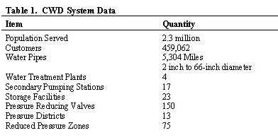
The CWD system is one of the ten largest public water supplies in the United States. Table 1 presents some of the pertinent information about the system.
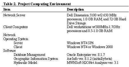
The first order of business in this project was to establish the computing environment that the project team would work under. This environment would then be re-established at CWD's offices at the end of the project. Although this environment was set up in 1999, it has continued to serve the project team reasonably well despite the rapid advances in hardware and software technology. Table 2 presents particulars of this setup.
Developing the database for the CWD water system required making a number of compromises between 3 different types of software that use databases. These three, H2ONet, ArcInfo and Oracle Enterprise, each have data models with conflicting requirements. CWD desired a database that strictly adhered to standards of normalized database design with rigid rules for referential integrity and data security. Oracle, with its rigid relational design, was selected. The hydraulic modeling software, H2ONet, has a data model that has evolved from the data requirements of the EPANet hydraulic modeling program, which itself evolved from flat data files. The project's GIS software, Esri's ArcInfo, has a more object-oriented data model built around managing the vast volumes of spatial data contained in digital mapping products. Because the project started from scratch with little or no digital data, the database development was a fairly fluid process. Also adding to this fluidity was the fact that at the start of this project, ArcInfo version 8 had not yet been released. So the full extent of what ArcInfo could and could not do were not fully known when the database design began.
PSpecific characteristics of each data model are described below:
* 3rd Normal Form
* Minimize data redundancy
* High level of data security and integrity
* Compatibility with a future City-Wide GIS
* Multiple tables with common ID's
* "Flat" data structure
* Import of data through data mapping via Open Database Connectivity (ODBC)
* Object-oriented
* Denormalized Data Model
* Inherited attributes
* Relationship Classes
The final geodatabase design represents a fusion (or fruit salad) of elements from each of these disparate data models. In keeping with the requirements of ArcInfo schema creation, the geodatabase design was based in MS Visio's Unified Modeling Language (UML). Esri's ArcFM Water data model was used as the basis for the project and it was merged with the conceptual relational database design developed on spreadsheets. The UML and spreadsheets were then kept up to date in parallel and the spreadsheets made up the metadata and data dictionary for the geodatabase. The end result is a multi-user geodatabase using Esri's spatial data engine (ArcSDE) with data storage in Oracle with two feature datasets (land and water), 47 features, 210 related object tables and 65 relationship classes. In terms of volume of data, it may not be the largest geodatabase, but it is certainly one of the most complex.
Once the database design was finalized, testing began with personal geodatabases using a small subset of the spatial extent of the CWD system. Although testing indicated that we had reached a workable compromise, scale-up to the full extent of the CWD system using the multi-user SDE environment revealed some challenging problems.
There are many aspects of the CWD database design, including many inherent features of ArcInfo, that have made the process of building hydraulic models easier. Specifically, these include complex edges, geometric networks, related tables and some of the custom GIS tools developed for the project.
Complex Edges - The complex edge feature allowed us to build the network with far fewer elements than traditionally included in a GIS dataset. Each pipe segment can have several spatial features connected along its length such as valves, hydrants, and corporation stops as illustrated in Figure 1. This aspect allows one to one correspondence between pipes in the GIS and pipes in the hydraulic model. Without it, pipes would have to broken at each of the over 300,000 fittings in the system.
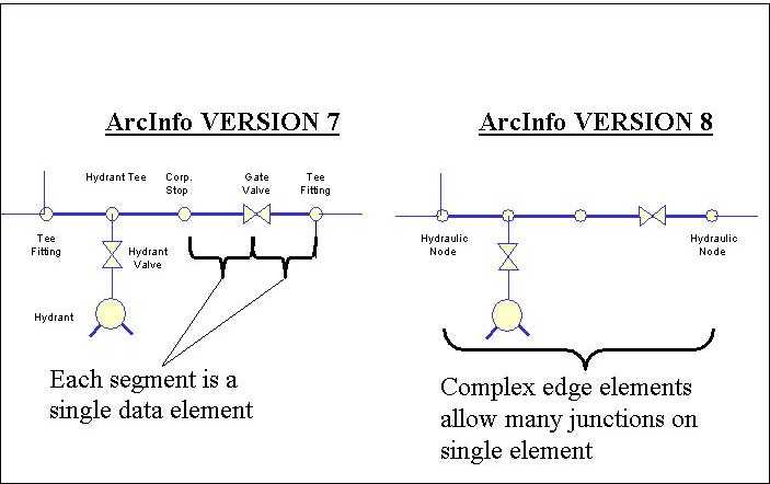
Figure 1. Complex Edge Example.
Geometric Network - Another key aspect of ArcInfo conducive to modeling is the geometric network, which virtually connects all of the pipes and attached fittings and features in the CWD system. This aspect allows preliminary analysis of the data to be modeled while in the ArcMap environment, rather than after the data have been exported to the H2ONet modeling environment. The geometric network allows for tracing through the network to check for pipe connectivity and to assess the impact of closing valves on other parts of the system or even on the same pipe.
Related Tables - One aspect of the original relational database design that has been retained is the use of related tables. These related tables allow commonly used attributes of selected features to be stored in a related table, which allows for simultaneous updates of similar features. Key examples are the "make tables." These tables describe typical attributes of certain features, such as the material, nominal and actual size of pipes, valves, pumps, etc., which allows for spatial elements to be initially input into the database with generic attributes. Then, when more is known, one record in a related "make table" can be updated which then cascades to all of the elements of similar make.
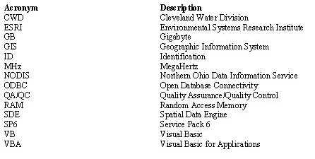
Custom Programming - With the help of Esri and NODIS, a number of custom programming tools were developed for use in the ArcInfo environment. Some of these tools were developed to add basic functionality to ArcInfo that was not originally available "out of the box" and other tools were developed to meet specific needs of the CWD project. Examples of the former include: tools to maintain archives of attribute values of spatial elements that have changed, tools that maintain a historical log of changes to the operating state of valves, and a tool to automatically assign elevations to features. Many of these eventually became part of the ArcInfo basic package. Examples of tools developed specifically for the CWD project include: tracing tools that help define unique pressure zones in the system, tools to trace the network and assess the impact of opening and closing valves, and tools to generate components of customers' service connections (corporation stops, service lateral, water meter and blind flange). These tools were all developed using either visual basic (VB), visual basic for applications (VBA), or C++ programming languages, which is functionality new to ArcInfo 8.
There are a number of aspects of the CWD geodatabase design that have been problematic. These aspects involve functions needed to work with hydraulic models as well as aspects of the relational database design that do not work well in the ArcInfo environment.
Persistent ID's - In order to best use the hydraulic models as a planning a nd maintenance tool, there is a need for persistent, unique identifiers of spatial elements in the system. These ID's are also used by the hydraulic modeling software. Thus, a section of pipe in a specific city block can be referred to by a given ID number and the results from hydraulic model simulations can be compared. However, in ArcInfo, the only unique ID that is maintained is the ObjectID, which is regenerated each time the geodatabase is compressed. Separate ID numbers have to be generated and maintained by the user. The problem with these separate ID numbers is that there is no inherent method in ArcInfo for ensuring that they are unique and nothing to prevent them from being changed. To avoid having duplicate ID numbers custom tools had to be developed that draw new ID numbers from a pre-generated set of ID's kept in a separate table.
Hydraulic Nodes - The basic components of hydraulic models are pipe segments connected at hydraulic nodes. To meet CWD's relational database requirements, hydraulic nodes were maintained as separate non-spatial objects related to certain spatially located fittings. Essentially, hydraulic nodes are found only at the endpoints of pipe segments. However, fittings are located all along the length of the complex edges that represent pipe segments. To avoid having multiple null values as foreign key attribute to the hydraulic node table, the geodatabase design used a foreign key field in the hydraulic node table to relate to the fitting feature table. However, finding the end points of a pipe segment, and then finding one unique fitting that is connected to that endpoint and associating that fitting with a hydraulic node has been a difficult task. Specific rules for creating fittings and nodes had to be developed and followed by the system users. Even with these rules, separate queries had to be developed to keep track of the hydraulic nodes to ensure that the hydraulic model software would execute properly.
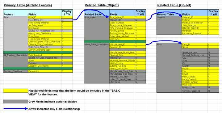
Multiple Related Tables - Because of CWD's relational database requirements, there are several levels of related tables in the project geodatabase. For example, pipes have related "make tables" and, in turn, "make tables" have related tables for material and for manufacturers. When ArcInfo 8 was first released, only once-related tables could be displayed using the identify tool or in ArcCatalog. A custom "Property Inspector" tool had to be developed that essentially redefined relationships between tables to create views of the data through multiple-related tables. An example of this is seen in figure 2, which illustrates the relationship between pipes and their related tables. In addition, this "property inspector" created custom views of the data displaying only selected fields of the related tables. Later versions of ArcInfo incorporated this tool into its base functionality.
Figure 2. Example of Property Inspector Specification
Bulk Editing and Tracking Edits - After testing the geodatabase with a smaller dataset using a personal geodatabase, one of the biggest problems confronted was in making edits in bulk in the SDE environment with geometric networks. For example, each of the over 55,000 pipe segments had to have a roughness coefficient associated with it. These roughness coefficients were assigned based on a number of rules related to age of pipe, material and lining. To traverse the entire pipe feature dataset to determine each pipe's age, material, and lining and assign a roughness coefficient proved to be impossible with a geometric network in place along with all of the relationship built into the geodatabase. After many long discussions with Esri, we proceeded with the bulk population of data into the geodatabase without the geometric network and with relationship classes included but not enforced. Some bulk edits even taxed the versioning capabilities of ArcSDE. In these cases, all user versions were reconciled and compressed and the editing was performed on the geodatabase's default tables with only the administrator having access to the geodatabase. Another issue confronted was keeping track of edits. CWD's desire was to maintain a log of all edits made to the geodatabase for record-keeping purposes. In doing so, the state of the system at some point in the past could be recreated for modeling purposes. In addition, tracking history and archiving allows CWD to back track if data input errors are made. It is reported that Esri will incorporate some type of historical tracking functionality in future releases of ArcInfo.
Demand Allocation - One of the key requirements of hydraulic modeling is to have an accurate representation of the geographic location of the customer water usage patterns. With over 459,000 customers, assigning their water demands to hydraulic nodes was a complex task especially given that the amount of data available for each customer varied. Ideally, each customer would be related to a specific parcel on the county assessor's cadastral maps. Custom tools were written by Esri to generate the main components of a customer's service connection between their parcel and the nearest pipe in the network. Once these service connections were generated, a separate tool developed by NODIS added up all of the demands associated with a particular pipe and assigned them to the hydraulic nodes at the end of the pipe in reverse proportion to the service connection's distance from the node. This process was very slow and incomplete; about 10 service connections per minute could be created, and some customer connections would be skipped. In addition, the process of assigning demands to nodes was an additional step that could not be done in a versioned environment and could only be performed on a fraction of the whole system at any one time. Only about 72 percent of the customers were able to have a service connection created this way. Others were able to be associated with parcels through address matching but there was still a significant amount of the customer base that could not be associated with a parcel and thus did not have a service connection drawn. These customers' demands were associated with a single pipe segment or a group of pipes based on their address or meter reading route. In summary, assignment of customer demands was a time consuming process that taxed the limits of the software and hardware's computing capabilities.
CWD's original desire was to have "one-touch" modeling capabilities. That is, they could select all or part of their system for modeling and, w ith one touch, export a data set to the hydraulic modeling software for hydraulic analysis of the system. Through the cooperative efforts of M&E, NODIS and Esri, a process was developed to select the data, export it from GIS, and import it into H2ONet. This process turned out to be more involved and time consuming than originally hoped. It is, however, functional and allows CWD to create hydraulic models from the most up-to-date system information in a matter of hours. It may be ugly in that it does not work as quickly and efficiently as originally hoped, but it is also beautiful in that it only takes a day or two to create a hydraulic model of all or part of the CWD system from a "live" geodatabase. It used to take months or years to create a model, which would then become obsolete as soon as any changes to the system are made.
It is the process of exporting data from the geodatabase where the benefits of proper planning in database design as well as the drawbacks related to the compromises are exhibited. The process involves multiple steps from selecting the data to be used to mapping the data into H2ONet.
Custom Export Tool - This tool was written by Esri to create an MS-Access database file that mirrors the data structure of H2ONet's data tables. Rather than rely on the geometric network or on relationship classes in the geodatabase, execution of this tool is strictly based on program code to search through the geodatabase, find the data needed and put it in the right tables for use by H2ONet. The specifications for this tool were based on meeting the business rules that govern the execution of H2ONet. Examples of these rules include: finding the fittings at the ends of pipes and then retrieving information on the nodes related to those fittings, finding all pumps and control valves associated with pipes in the geodatabase, exporting different types of information from control valve tables in the geodatabase depending upon values in different fields. In many cases, field values from several tables in the geodatabase were used to generate one table for use in H2ONet or one table in the geodatabase was used to generate field values in several H2ONet tables.
Selecting Data for Modeling - Prior to running the export tool, the user must first select the part of the network that is to be modeled. Esri created a custom tool called "selection to table" which takes a selected set of pipes and saves the pipeID's as a new table called a "geometry scenario." In general, the selection set includes a spatial selection or an attribute-based selection set based on one or more hydraulic zones (a series of pipes connected without any pressure regulating device such as a pump or control valve). M&E developed a code-based input form (as shown in Figure 3) in which the user enters information pertinent to the specific modeling run being exported: hydraulic zone(s), demand condition (maximum or modal day), time period and duration of run, and water quality related data. Data input in this form is stored as field values in a single record of the table called "Modeling_Run."
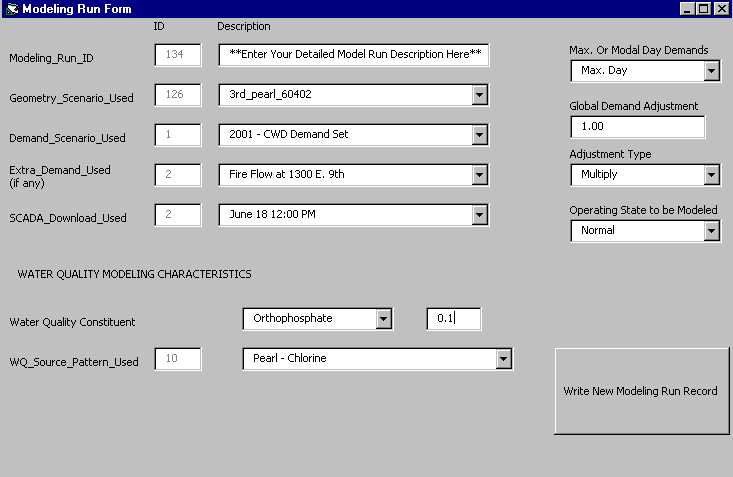
Figure 3. Model Run Input Form
Export Process - After the above two steps are completed, the user then runs the H2ONet export tool developed by Esri. They then have to wait. The length of time to complete an export depends upon the number of pipes included in the selection set. A set with 10,000 pipes took 8 hours of computer time to complete. Smaller data sets take less time. One of the most frustrating aspects of this project was the execution of this tool due to errors in either the code or the data that would cause the tool to abort execution. Only after numerous failed attempts to export, were a number of procedures added to the code to capture, log and/or ignore errors in the data such as missing or invalid field values or missing related features. The tool now runs reasonably well providing a log of the export process, export statistics, and a listing of feature ID's where errors were detected.
ODBC Mapping Process - H2ONet is one of the leading hydraulic modeling software products in the industry. Yet, M&E did not recommend H2ONet to CWD for use on this project. The reason was that H2ONet could not import all of the data that was to be contained in the project geodatabase for use in modeling. H2ONet was selected after they developed an ODBC exchange module that allows the user to import data from an external database source. Even still, the mapping of model data into H2ONet is not an automated process. The user must go to the exchange module and, for each H2ONet table, map the fields in the MS-Access database table exported from GIS to the corresponding fields in H2ONet. As mentioned above, the MS-Access tables mirror the H2ONet tables. This process takes about 30 minutes regardless of model size.
In a related development, M&E developed a modification to Esri's export code that creates *.dbf files that mirror H2ONet's *.dbf file structure that can be copied directly to a folder users by H2ONet to eliminate the time spent in the mapping process. However, this method is more sensitive to errors and does not allow viewing of the data to inspect for errors and is still being tested.
M&E has successfully exported and run models of the CWD system subdivided into eight zones consisting of one or more hydraulic zones. Figure 3 shows the geographic location of these zones. We are proceeding to calibrate the results of the hydraulic models against data collected in the field.
If we could have been able to see into the future, this project may have progressed differently. However, because of this project, many changes in ArcInfo and in H2ONet were made that now benefit everyone using these software packages. So, in a way, GIS and hydraulic modeling technology would not be where it is today without it. In hindsight, here are a few of the lessons learned from this unique project:
* It was important to set up the geodatabase so that hydraulic models could be generated with relative ease. At its heart, there is a one-to-one correspondence between pipes in the geodatabase and pipes in the hydraulic model.
* It is very important to be firm when dealing with software developers. If it does not work, ask why not. If you want the software to do something it cannot do, insist that it be changed. Often, the changes will be made and will improve the software.
* It would have been more advantageous to approach the development of the database from the ArcInfo and ArcFM framework and add relational database features rather than start with a relational database and try to make it conform to the ArcInfo's object model. Some of the performance issues we have to deal with may have been avoided.
* Expect that there will be errors in the data and be diligent in trying to capture them wherever they can exist. What may be represented in a GIS without error may not work in a hydraulic model or it may allow you to run hydraulic analyses, but the results do not make sense.
* If custom programming is needed, make it as open and flexible as possible. Most of the code written for this project that would be used on an ongoing basis was able to be used with SDE or personal geodatabase and was mindful of network access and security issues.
The development of a geodatabase for Cleveland's water distribution system has been a long, interesting journey. We started with the goal of meeting the client's requirements of a relational database geared for hydraulic analysis. We made the journey using divergent types of software with database requirements that often were in conflict with CWD's database requirements as well as with each other's. The end result, however, is a workable geodatabase that catalogs CWD's system assets as well as keeps track of operations and maintenance activities while allowing hydraulic models of their distribution system to be developed with relative ease.
In the future, CWD plans to use this geodatabase to keep a "live" representation of the system by keeping track of valve positions, logging customer complaints and maintenance activities. The many custom tools developed for this project will need to be kept in line with perpetual series of software upgrades that will occur. In addition, QA/QC procedures put in place by M&E during data population must be followed as the system grows and changes.
There have been a number of recent developments in hydraulic modeling software packages, such as MWHSoft's H2OMap and Haestad Methods' WaterGEMS, that use a much tighter link between GIS and hydraulic models. However, the fact remains that the geodatabase design must closely parallel the data model of the hydraulic modeling software for optimal effectiveness. Further, the data needs for hydraulic models will generally be different from those of an enterprise-wide database tailored to meet multiple needs over and above hydraulic modeling.
The authors would like to thank Mr. Pierre Haddad, Ms. Ramona Lowery, Mr. Guy Singer and Mr. Alex Margevicius of the Cleveland Division of Water who have worked with us throughout the project to help define the system requirements and test the applications. We would like to thank Dr. Mark Salling, Ms. Ellen Cyran and Mr. James Wyles of NODIS for their efforts in converting CWD’s data and for helping build and test the geodatabase. Special thanks to Ellen for her tireless efforts wrestling with UMLs and for developing the code for assigning demands to pipes. We would like to thank Mr. Brian Hoefer and Dr. Dean Djokic of Esri’s Redlands offices for their help in developing many of the custom tools used in this projects, especially the H2ONet export tool. Thanks also to Mr. James Moening of Esri’s Columbus office for his help in troubleshooting the installations at our offices and at CWD’s offices.