| M.J. Mineter, S. Dowers, B.M. Gittings Department of Geography University of Edinburgh Drummond St Edinburgh EH8 9XP Scotland {mjm, sd, bruce} @geo.ed.ac.uk http://www.geo.ed.ac.uk/research |
D. Caldwell |
The paper describes a research effort by the Parallel Architectures Laboratory for Geographical Information Systems at the University of Edinburgh. The goal of the research was to develop and use a prototype, multicomputing software architecture for visibility analysis. The multicomputing software architecture executes multiple Workstation ArcInfo commands concurrently on networked processors, using spare CPU cycles to reduce the elapsed time for the analysis. A Masked Area Plot (MAP) is calculated for every elevation post in a Digital Elevation Model (DEM). The individual Masked Area Plots are combined in a compact database, called a Complete Intervisibility Database (CID), which is exploited by a series of tactical decision aids to determine cumulative, maximum, and multi-observed visibility.
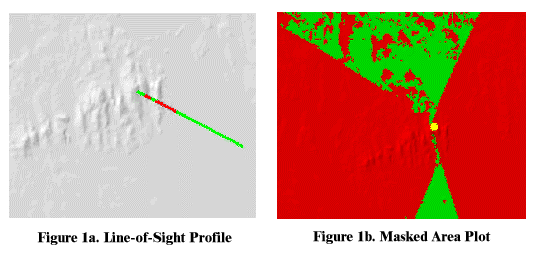
Two important innovations resulted from this research. First, the use of ArcInfo in a multicomputing environment opens up new possibilities for spatial analysis. By exploiting the untapped potential computer power in offices with multiple computers, previously difficult applications can be addressed and new applications can be developed. Second, the CID represents a new and important tool in understanding the structure and visibility characteristics of the terrain.Intervisibility describes the effects of terrain on visibility. It is a key factor in military terrain analysis and impacts a soldier’s field-of-view, viewing distance, and engagement ranges. Two visibility products are currently available: Line-of-Sight Profiles for point-to-point analysis (Figure 1a) and Masked Area Plots for multiple point viewshed analysis (Figure 1b). In the examples below, green indicates visibility and red indicates no visibility from the observer's position (marked in yellow in 1b).
 |
This project expands the number and type of visibility analysis products. Within a multicomputing framework, researchers developed a Complete Intervisibility Database (CID) consisting of the Masked Area Plot information for all posts in an elevation model. The CID serves as the basis for a new generation of visibility tactical decision aids.
The four goals of the research effort were to
With the goal in mind of running large numbers of visibility analyses, the first task was to decide on the appropriate computing architecture. A multicomputing approach, which was achieved by running concurrent visibility analyses on multiple computers, was selected over an approach that parallelized each individual analysis operation or a hybrid parallel/multicomputing approach.
Speeding the execution of one visibility analysis by using multiple processors was less efficient than running multiple processors each on one visibility analysis. In general, parallelism is most efficient when applied at the highest practical level. Given that 9828 analyses were required for the test, no benefit would have been derived from the low level parallelism until more than this number of processors was available. Furthermore, the approach would work with larger data sets and correspondingly more tasks.
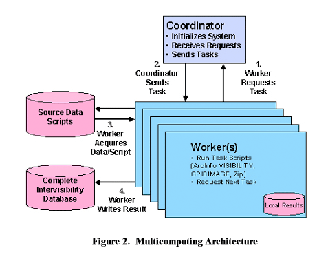
The initial multicomputing design was implemented using a task farm approach in a standard UNIX environment, with PERL scripts, Workstation ArcInfo, AMLs, rcp, rsh, and shared directories for storing scripts, source data, and results. The architecture includes a coordinator process and multiple workers (each comprising a different processor).
The coordinator starts the process by downloading initialization scripts to the users, via rcp. The scripts, which are run by rsh, copy data files and AMLs from shared directories to the worker's own space. Once the workers are initialized, the coordinator responds to worker requests for tasks, allocating the tasks to available workers. This approach accommodates the changing availabilities of processors, due to other computation requirements or the different speeds of processors. There is no pre-allocation of particular tasks to particular workers. The coordinator also monitors the status of ongoing jobs and closes the operation when all tasks have been completed.
The workers request tasks, carry them out, and copy the the results to the
shared directories of the database. Each worker is a CPU associated with a valid
Workstation ArcInfo license. ArcInfo is invoked from a PERL script. An AML copies
the source elevation data, removes null values, and creates a temporary point
database for the 16 observers. The visibility analysis is performed using the
Workstation ArcInfo VISIBILITY command. The VISIBILITY command supports the
simultaneous visibility analysis from 16 observation points, thus reducing the
number of times the command must be run. Observation points are processed using
sub-grids of 4 X 4 points. The worker runs the VISIBILITY command, converts
the resulting grid converted to a BIL image, and compresses the BIL image using
zip. After completing the analysis, the worker deletes the temporary files and
writes a trace file documenting the success or failure of the operation.
|
The initial design was implemented in a UNIX environment to demonstrate the concept and speed the development. Ongoing efforts will expand the architecture to work in UNIX, Windows, and mixed environments.
The Complete Intervisibility Database (CID) represents a new concept in terrain analysis, so the design and development of a storage format was one of the initial tasks. The focus of the design effort was to develop a simple structure that would facilitate rapid access to the data. Rapid access was emphasized over a minimization of the storage requirements. After an evaluation of several alternatives, a directory and file based solution was selected, using zipped BIL files containing the output of the ArcInfo VISIBILITY command.
The source data for the CID is a regular square grid containing elevations at each a post in the center of each grid element. There are nCols x nRows posts in the grid. A Masked Area Plot (MAP) for the post at column i and row j, MAP(i,j) contains a binary value for each post in the grid indicating whether that post is visible from the originally selected post. The MAP therefore contains nCols x nRows binary values and the simplest representation is an nCols x nRows array of bits. A CID is a collection of MAP(i,j) for each post in the original grid. There are therefore nCols x nRows MAPs in the CID and the total size is nCols x nRows x nCols x nRows bits. For an input grid of 336 columns by 466 rows, the CID is 24,516,043,776 bits or 2.9Gb. The size of this suggests that some form of compression is desirable.
ArcInfo can process up to 16 observer points in one command, the result being
stored in an integer grid with 16-bit values where each bit represents an observer.
By selecting the 16 observers in a 4x4 subgrid of the original grid, we can
expect there to be significant correlation between the bits in a 16-bit word,
which will aid in compression. Further processing of MAPs can also be simplified
with this form of representation since each 16-bit value corresponds to the same observed post,
reducing the need for unpacking
single bit values. The collection of 16 MAPs together is called a MAP16 and
is identified by the column and row of the top-left observer. There are therefore
~(nCols/4) x (nRows/4) MAP16s in the CID. For a 336 by 466 input grid there are
9828 MAP16s. The MAP16s are generated in binary form by converting data from
ArcInfo GRID to BIL format.
Rather than develop specialized compression techniques, the research team investigated
commonly used compression software. Initial tests with very sparse MAPs showed
compression factors of between 100 and 300. Based on this, the team decided
to use a very simple database structure based on directories in the native file
system. Each row of MAP16s is allocated a separate directory named from the
row number. Each directory contains a zip file for each MAP16 in the row with
the name based on the column number of the MAP16. The zip file contains a single
compressed BIL representation of the MAP16. The top directory of this structure
also contains a header file describing the original DEM, projection information,
and a missing value mask. This resulting database structure has the advantage
of simple random access to any MAP16 and expansion is achieved using standard
tools available on almost all computing platforms.
The University of Edinburgh researchers demonstrated the multicomputing architecture by creating a Complete Intervisibility Database (CID) for a U.S. Geological Survey 1:24,000-scale Digital Elevation Model (DEM).
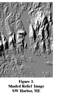
The Southwest Harbor, Maine, quadrangle source data, shown in Figure 3., was the test dataset. It is a relatively small DEM with 466 rows and 336 columns, generating 156576 Masked Area Plots for the CID. All told, 9828 tasks were required.
The complete database was built in 43 hours and 26 minutes using 13 processors, of which 5 were 300MHz Sparcs, the remainder being older Digital processors. On a SUN Sparc 300MHz processor, most runs took between 117 and 130 seconds. A single run performed the visibility analyses for a block of 16 points. In a typical run of 124 seconds, the observer point extraction took 5 seconds, while the visibility analysis took 117 seconds. Each processor used in excess of 90% of its CPU time in running the tasks, with run times of between 2 and 5 minutes, depending on the processor. The variation in performance between the processors is clear: the pattern was consistent in all runs.The efficiency of use of each processor demonstrates the effectiveness of the task farm.
The final database, with each file separately compressed, is 84Mbytes i.e., approx 3% of the raw 4-D bitmap size (2.9Gb). It comprises 9828 files, with 84 files in each of 117 directories (one directory per row).
Exploitation software, written in Java, generates three tactical decision aids, including a Cumulative Visibility Plot, the Post of Maximum Visibility Table, and a Multi-Observed Masked Area Plot.
a. Cumulative Visibility Plot. For each post in the DEM, the cumulative visibility can be calculated. Two types of cumulative visibility plots can be generated: a Cumulative Visibility - Observer and a Cumulative Visibility - Observed. The result of a cumulative visibility analysis is an integer grid.
 The
Cumulative Visibility - Observer Plot records the number of grid posts visible
from the observing grid post. This is simply a count of the number of visible
posts in the Masked Area Plot centered on the observing grid post.
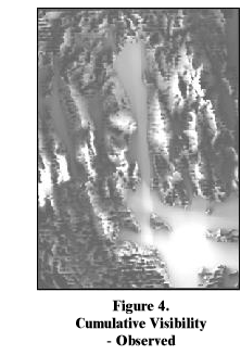
The Cumulative Visibility - Observed Plot records the number of times a given post is observed. It is a count of the number of Masked Area Plots in which the post is visible. Figure 4. shows an example of a Cumulative Visibility - Observed Plot. Areas of greatest visibility are shown in white, while areas of limited visibility are shown in black.
Since intervisibility is not necessarily symmetric, the Cumulative Visibility - Observer Plot may differ from the Cumulative Visibility - Observed Plot.
Cumulative visibility is interesting, because it reveals the structure and
pattern of intervisibility characteristics within a dataset. The highest points
are not necessarily the most visible points and the extents of the dataset influence
the cumulative visibility results. The cumulative visibility surface can be
used as a cost surface for routing applications, where it provides the basis
for determining the least or most visible routes between locations.
b. Post of Maximum Visibility Table. For each post in the DEM, the post of maximum visibility can be calculated. This application creates a table that stores the location of the grid post, the location of the post which observes the grid post and sees the largest number of other posts, and the number of posts seen from the post of maximum visibility. The results are stored in a table, rather than a grid, because there may be multiple posts having the same maximum visibility value.
The Post of Maximum Visibility Table is helpful for identifying observer positions. By selecting the post of maximum visibility, the observer not only sees the target post, but the observer sees more additional posts than any other location observing the target post.
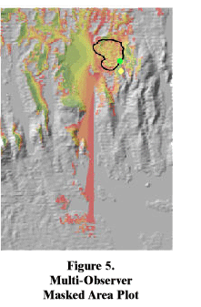
c. Multi-Observed Masked Area Plot. The inputs for the Multi-Observed Masked Area Plot are a binary grid and the Complete Intervisibility Database (CID). The binary grid defines a target area and contains a 1 for each post in the target area. The target area in the binary grid can be used to represent point, line, or area features that are continuous or discontinuous.
 For each
grid post location in the CID, the Multi-Observed Masked Area Plot counts the
number of posts in the target area of the binary grid which are visible. The
result is an integer grid that can be divided by the count of posts in the target
area of the binary grid to give a percentage of the target area that is visible.
Figure 5 shows an example of a Multi-Observed Masked Area Plot. The target area in this example is displayed by its polygonal boundary. The areas displayed in red view the smallest portion of the target area, while the areas in green view the largest portion. The green dot is the location within the polygon that sees the greatest portion of the target area, while the yellow dot it the location outside the polygon that sees the greatest portion of the target area. In this case, the point outside the polygon sees more of the target area than the point inside the polygon.
The Multi-Observed Masked Area Plot is useful for identifying locations with maximum visibility of line and area features. For example, it could be used to site an observer who wishes to have the largest viewing coverage of a road, a lake, or some other linear or areal feature.
The tactical decision aids described above were developed to show the potential of the CID for expanding our understanding of the relationship between intervisibility and terrain. Researchers anticipate that the CID will be the basis for the development of additional tactical decision aids.
This research project clearly demonstrated the viability of a multicomputing architecture for spatial analysis, as well as the potential for a new series of visibility products. The multicomputing architecture was based on the use of Workstation ArcInfo operating on a UNIX network with standard UNIX tools. It is ideally suited to office environments with multiple ArcInfo licenses. The approach not only makes the fullest use of resources during working hours, but taps the vast potential of computing resources during off hours. Application of this computing paradigm will result in new and innovative products and services.
This research has also validated the concept of the Complete Intervisibility Database (CID). The pre-calculation of Masked Area Plots for a DEM means that visibility information can be accessed directly and need not be calculated for every application. The CID serves as the basis for studying the fundamental relationships between elevation data and visibility, while the Cumulative Visibility Plots, Post of Maximum Visibility Table, and Multi-Observed Masked Area Plots are the first in a new generation of visibility tactical decision aids.
This research was sponsored by the U.S. Army Engineer Research and Development Center, Topographic Engineering Center, Alexandria, VA, and the U.S. Army European Research Office (ERO), London, England, under ERO R&D 8707-EN-01, Contract N68171 00 M 5807.