William Duffy
Stephen M. Dickson

USING GRID AND GRAPH TO QUANTIFY AND DISPLAY SHORELINE CHANGE

  ABSTRACT

  When faced with displaying subtle shoreline changes, coastal geologists are
often forced to choose between two compromises.  They can use very large scale
maps that capture the detail but display only a limited portion of the
shoreline at a time.  Or they can average the change for various shoreline
segments and display these less detailed data in graphic form next to a map of
the coast.
  This paper will describe a methodology for preparing and displaying
shoreline change data digitized from ortho-corrected aerial photographs of
Maine's coast.  By using GRID and the Arcplot GRAPH commands, all the detail of
the original data is maintained on maps of a reasonable scale.  Once the data
are in this format, it is also easy to resample them at various intervals for
use in erosion rate models being used to develop coastal setback zones in
Maine.

  INTRODUCTION

  Coastal erosion is a problem throughout the U.S., occurring on both the
east and west coasts, the Gulf shore, and the Great lakes.  In Maine the worst
coastal erosion often occurs during "nor'easters"; winter storms usually
lasting six or more hours and characterized by strong northeasterly winds.
Rising sea-levels and poorly-sited coastal development acerbate the
problem.
  In 1992 the Maine Geological Survey (MGS) received a grant from the Maine
State Planning Office under the Coastal Zone Management Act of 1972 to develop
a series of maps identifying regions of high coastal erosion in Maine.  These
maps and the data used to create them would document the rate of coastal
erosion and be used to develop coastal setback zones in Maine.

  DATA COLLECTION

  The Maine Geological Survey began the study by collecting sets of circa
1950 and 1990 aerial photographs for 30 Maine beaches.  Using a computerized
analytic stereoplotter system at the University of Maine, the 1:5000 to
1:30,000 scale film diapositives were magnified 16x and the seaward dune
vegetation lines were digitized.  All data were converted to UTM coordinates
using known ground control points and standard aerotriangulation and orthophoto
correction techniques.  These methods produced sets of 1950 and 1990 coastline
data for each beach.  Comparisons between common points on each set of photos
showed positional accuracy of one meter or better.  Finally, using the DXFARC
command the coastline data were converted to ArcInfo coverages.

  USING GRAPH AND GRID

  While the coastline coverages for a particular beach contained highly
detailed positional data, it was difficult to see subtle changes at anything
other than large scales.  We decided that a better way to display the detail
recorded in these data was to use the GRAPH commands in the ArcInfo Arcplot
module.  GRAPH commands use two fields from an attribute table as the X and Y
coordinates of a line or area graph.  To display the attributes, the user
specifies a GRAPH EXTENT which sets the length of each axis in page units.  By
specifying a large value for one axis with respect to the other, the data
displayed can be stretched to make subtle changes visible.
  With the coastline erosion data, we wanted to use the length of the
coastline as the Y-axis and the change in coastline positions between 1950 and
1990 as the X-axis.  The tricky question was how to get this change information
from the two coastline arcs.
  In most vector based GIS software, like ArcInfo, arcs and polygons have
topology, i.e., they have information attached to them which record their
beginning and end points, and left and right sides (for arcs) or their inside
and outside (for polygons).  Topology makes it possible to assign addresses to
a street arc or to find how many addresses there are within a town polygon.
However, topology gives us no information as to what is going on in the empty
space around an arc or outside a polygon.  Information is only recorded for the
coordinates that form the arc or polygon.
  In the GRID module of ArcInfo information is not tied to specific features
like arcs or polygons.  Instead, all data are referenced to a fixed location or
cell whose size is defined by the user. Individual cells can be coded with
values just as arcs or polygons are; however, there is no empty space in a grid
coverage, all cells contain at least the coordinates of their location.
Because of this, we can move anywhere in a grid coverage and get information
such as "How far am I from the nearest cell coded as 1950?"  And this was
precisely the question we needed to ask.

  MAKING GRIDS

  To the uninitiated creating and manipulating grids can be a daunting task.
However, with a little experience, using grids soon becomes second nature.
With simple commands, grids can be created from arc or polygon coverages and
vise versa.  A new grid can be created by applying one or more statistical or
logical functions to another grid.  A third grid can be created by simply
adding two other grids.  Grids provide a set of powerful tools for the analysis
of geographic data that vary continuously over a region.
  In the first step of our analysis, the LINEGRID command was used to convert
both coastline coverages to grids with a one meter cell size.  In the resulting
grids, cells which fell at the position of the 1950 or 1990 coastline were
coded as "1950" and "1990", respectively.  All other cells were coded as
NODATA.
  Next, the EUCDISTANCE function was used to create a new grid from the 1950
coastline grid.  This function calculates the distance of every cell in the new
grid to the nearest occurrence of a specified value in the original grid.  In
this case the specified value was the code "1950" in the 1950 coastline grid.
The resulting grid looks like a buffer around the original 1950 coastline grid
(Figure 1). However, unlike a buffer polygon, this buffer was composed of
individual cells, each of which contained a distance value.
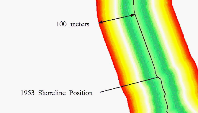
Figure 1. Euclidean Distance Grid.  Grid cells have been color
coded to reflect distance from 1953 shoreline.

  A third grid was then created by intersecting the distance grid with the
1990 coastline grid created earlier.  The intersection was done using the
conditional statement:  "If the coastline grid cell contains the code "1990"
put the value of the distance grid at that location in the new grid, otherwise
put a NODATA value there".  The result of this statement was a grid containing
the distance to the nearest 1950 cell at the position of each 1990 cell.
  The final step was to convert this last grid back to an arc using the
GRIDLINE command.  Unlike the original coverage, which contained only a few
arcs connected at pseudonodes, this new arc coverage consisted of hundreds of
short arcs, approximately one meter in length, connected at pseudonodes.  Each
of the short arcs represented the 1990 coastline position and contained a code
for its distance from the 1950 coastline.
While the above procedure may seem complicated, it required only five
commands to execute.

  BACK TO GRAPH AND MAPS

  The resulting arc coverage contained the change in coastline position
between 1950 and 1990 (the X-axis information) for each segment of its length
(the Y-axis information).  This information could now be used to produce a
graph showing both the obvious and subtle changes in coastline position in 40
years.
  An example of one map and graph is shown in Figure 2.
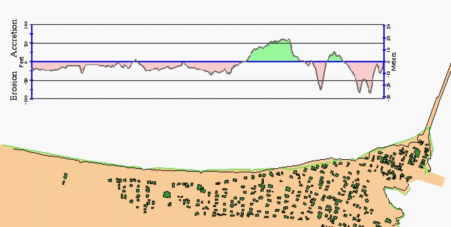
Figure 2. Camp Ellis Beach, Saco, Maine.  The 1991 coastline position is shown in
black, the 1953 coastline is green. North is to the left and a portion of a large
jetty, built to stabilize the mouth of the Saco River, is shown at the south end
(right) of the beach. The graph shows the extent of erosion which has taken place
over 38 years. Most of the beach shows a net loss of material.  The two major areas
of accretion are due to seawall construction made in an attempt delay the retreat
of the shoreline near houses.  The building footprints, shown in dark green, were
digitized prior to 1991 and since then three buildings have been destroyed during
winter storms.

  Many fine details are apparent on the graph in Figure 2 which are hard to see
on the adjacent map.  Using the graph data, average erosion rates can be calculated
for individual beaches making it possible to compare coastal changes in
different regions.  In addition, the graph data can be resampled and averaged
based on various criteria, such as vegetation type or beach orientation.

  CONCLUSIONS

  The GRID and GRAPH techniques described above have substantially increased
the amount and improved the quality of data being extracted from an arc data
set.  At the same time, the display of the data in a graphic form shows clearly
the extent of the coastal erosion problem in Maine.  We hope these data can be
used to improve public policy on coastal hazards related to coastline
change.

  ACKNOWLEDGMENT

  This project was made possible by financial assistance from the Maine
Geological Survey, Department of Conservation, and from a grant through the
Maine State Planning Office under the Coastal Zone Management Act of 1972, as
amended, pursuant to Award #NA37OZ0263-01 administered by the Office of Ocean
& Coastal Resource Management of the National Oceanic and Atmospheric
Administration.  Data for this project were gathered by the Department of
Geological Sciences and the Department of Survey Engineering at the University
of Maine.  Data analysis and map production were done at the Maine Office of
Geographic Information Systems.

William Duffy, Programmer Analyst
Maine Office of Geographic Information Systems
Station #22, 71 Hospital St.
Augusta, ME 04333
Telephone: (207) 287-6375
Fax: (207) 287-7641
E-mail  iswduff@state.me.us

Stephen M. Dickson, Marine Geologist
Maine Geological Survey, Dept. of Conservation
Station #22
Augusta, ME 04333
Telephone: (207) 287-2801
Fax: (207) 287-2353