USE OF GIS IN THE FEDERAL EMERGENCY MANAGEMENT INFORMATION
SYSTEM (FEMIS)
S. Tzemos, R.A. Burnett
Use of GIS in the Federal Emergency
Management Information System (FEMIS)1
Abstract
The Federal Emergency Management Information System (FEMIS) is a decision support
system that integrates all phases of emergency management. FEMIS is designed to
support the emergency manager in planning, coordination, response, training, and exercise.
FEMIS uses a classic client-server architecture. The FEMIS component modules include
a Human-Computer Interface (HCI), a relational database management system (RDBMS),
an electronic mail system, a report generator, a project management system, a geographic
information system (GIS), and hazard specific modeling and analysis tools. Of these
systems, the RDBMS and the evacuation model reside on a Unix platform. All other
software resides on networked personal computer (PC) workstations.
ArcView 2.0 is the GIS product used to support FEMIS at each PC workstation.
ArcInfo is loaded on the Unix-based server and is used to prepare the spatial data.
This paper describes the way GIS support for FEMIS was built using Avenue scripts and
the inter-process communications available through ArcView 2.0. It also identifies the
limitations encountered and the way the HCI was built to overcome them. The final
product is a fully integrated responsive, user-oriented decision support system, capable of
linking the planning, response, recovery, and mitigation phases of emergency
management.
1.0 Introduction
The Federal Emergency Management Information System (FEMIS)[PNL1] is a
client-server based decision support system that automates and integrates the planning,
coordination, response, training, and exercise phases of emergency management. FEMIS
provides the planner with integrated tools to generate and distribute emergency plans,
track resources, collect and use real time data from weather monitors, generate event logs
and status boards, display the location of real or potential hazard events via a geographical
information system, model and display plumes of hazardous material releases, animate
plume movement over time, determine and display areas at risk, automate the formulation
of protective action recommendations and decisions, generate and display evacuation
routes, simulate anticipated traffic conditions during emergency evacuation, and more.
FEMIS speeds response when time is critical, permitting planners and operators to quickly
evaluate and implement emergency response plans, thereby reducing the risk to the
population.
FEMIS is designed to be a decision support tool with applications across a broad range of
disaster planning and response activities. The U.S. Army's Chemical Stockpile
Emergency Preparedness Program (CSEPP) and its associated requirements, functionality,
and interfaces provided the target application environment for the initial FEMIS system
implementation.
This paper briefly discusses the implementation philosophy and functionality of FEMIS as
a background for a more detailed discussion of the spatial data model and functionality of
the GIS portion of FEMIS as implemented in ArcView Version 2.0. The paper concludes
with a discussion of implementation issues and lessons learned.
2.0 FEMIS Architecture
FEMIS uses a client-server architecture as shown in Figure 1. ORACLE, a relational
database management system, is used to implement the FEMIS database (FDB). As
installed at a given site, the FDB may be distributed logically among multiple Emergency
Operations Centers (EOCs) and physically among multiple networked Unix server
workstations. The ArcInfo Geographic Information System (GIS), used for spatial data
preparation and conversion, also resides on a Unix server, along with electronic mail
services, an event notification system, and an evacuation network simulation model.
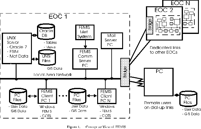
A communications server, implemented on a dedicated personal computer (PC)
workstation, is used to acquire meteorological (met) data. The communications server
receives met data over a serial port from a Handar weather system during actual
operations, or from a met simulator (a PC workstation dedicated to sending canned
weather data previously captured from a Handar system) during training exercises. The
communications server can also be interfaced to other external communication systems
and devices.
The controlling FEMIS application and user interface, the end-user GIS (ArcView 2.0),
and other supporting subsystems and models operate on each client PC workstation under
Microsoft Windows. The FEMIS application software is implemented in Visual Basic and
controls access to the subsystem software and the relational database. The subsystems are
built upon commercial off-the-shelf (COTS) software products and industry standard
models as listed in Table 1. The FEMIS application communicates with its subsystems
through shared Dynamic Link Libraries (DLL), Object Linking and Embedding (OLE),
Dynamic Data Exchange (DDE), or a custom messaging service, depending on the
interprocess communication options available in each subsystem.
All GIS interactions are performed through DDE calls from the FEMIS application to
ArcView Version 2.0. The FEMIS application sends a DDE "execute" request to ArcView
with the name of the Avenue2 script to be executed and a parameter string. ArcView
executes the script and sends back a DDE message with the results from the script
execution and a status code.
3.0 FEMIS Functionality
FEMIS employs a windows-based user interface that facilitates the selection and use of
emergency information, analysis, and planning tools without unnecessarily restricting the
user to a monolithic sequence of choices. At the heart of the FEMIS application is the
navigator screen, shown in Figure 2. The navigator screen provides systematic access to
the FEMIS subsystems and application models. The appearance of the navigator screen,
the options available to the user, and the actions resulting from those choices are
dependent upon the current emergency management mode (e.g., planning, operations,
exercise/training) and other prior user selections, external events, and conditions which
may be present.
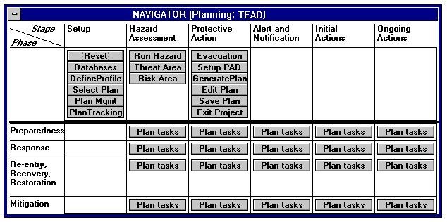
Planners at an EOC will use FEMIS in the Planning3 mode to develop a suite of
emergency plans based on various potential accident (event) scenarios. For any given
scenario, a user may elect to apply an existing emergency plan (Select Plan), modify a
plan (Edit Plan), or create a new plan (Generate Plan). If the EOC were notified of a real
emergency event (e.g., a hazardous material release), EOC personnel would need to
immediately switch to the Operations mode of FEMIS so that they could begin to analyze
and respond to the emergency situation at hand. The Run Hazard option allows
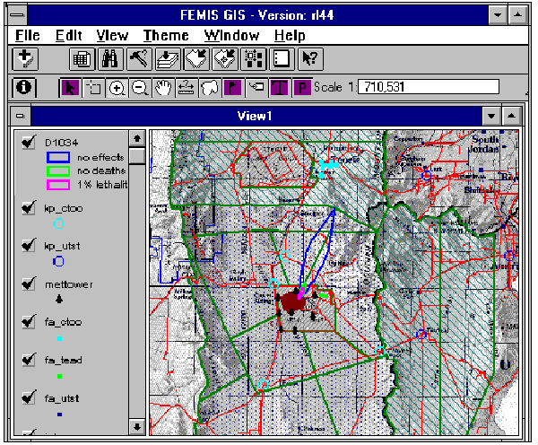
emergency personnel to run a hazard dispersion model (see Section 4.2) and plot the extent
of the predicted plume, as shown in Figure 3. Emergency personnel may choose to view
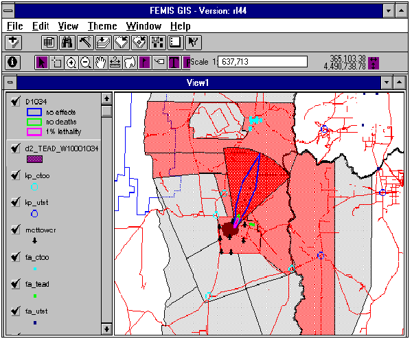
the Threatened Area (Figure 4) and obtain estimates of the population at risk and the time
when the hazard is expected to reach each of the affected zones and facilities. They may
then select a specific emergency plan and make the appropriate protective action decisions
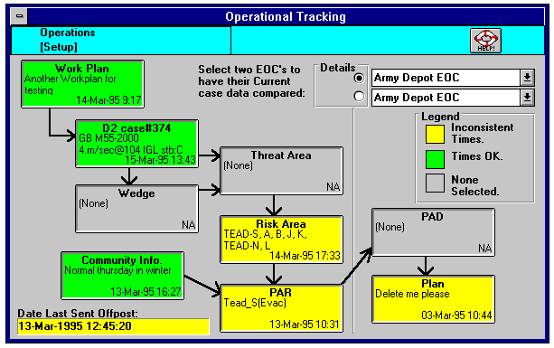
(e.g., evacuation or sheltering). Operational Tracking (Figure 5) may be invoked to track
the overall status of emergency operations. Detailed information on the event, weather
conditions, casualties, evacuees, and other topics can be obtained from status boards under
the Status option.
The Evacuation option provides access to an evacuation network model (see Section 4.6)
for evaluating the consequences of evacuation decisions. The evacuation simulator model
ESIM[ORNL] forecasts the loading of the evacuation network links based on traffic loading
and roadway network topology. Traffic loading is determined by weather, population
distribution, and other conditions at the time of the emergency event. The network
topology can be quickly modified to account for road closures, accidents, or other
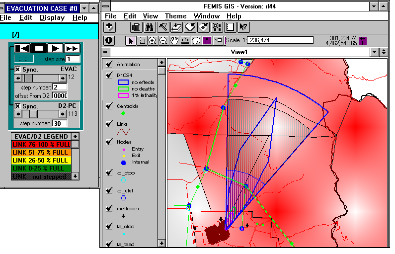
problems. The results are best depicted through Animation of the evacuation network,
synchronized with animation of the hazardous material dispersion. Figure 6 shows an
animation snapshot.
4.0 GIS Functionality
The FEMIS GIS map display, implemented as a view within an ArcView project, includes
a scanned image map of the area of interest, together with themes that represent readily
identifiable features, such as roads, streams, water bodies, and political and administrative
boundaries. These features provide a background and spatial frame of reference for the
display of features and events (e.g., facilities, traffic control points, emergency planning
zone boundaries) that are relevant to the emergency management process.
The FEMIS application, written in Visual Basic, controls the programmatic interface to the
GIS. A Map button on the toolbar of the main FEMIS screen is always visible and
provides access to ArcView to perform general ad hoc mapping functions. In addition,
context-sensitive map buttons found in many of the application screens invoke the GIS to
perform special map display and selection functions that are specific to the FEMIS
application.
The GIS is used to create and display graphic representations of the potential dispersion of
hazardous substances following an accidental release to the environment. Emergency
planners can use the GIS to display, identify, and analyze the spatial relationships among
possible event locations, shelters and other emergency management facilities and
resources, transportation routes, and population at risk. The GIS can also animate the
progression over time of both the hazard plume and the evacuation of the affected area.
These and other GIS functions currently implemented in FEMIS are discussed in the
following paragraphs.
4.1 Location Identification and Spatial Analysis
By selecting the map button located on many of the FEMIS screen forms, the user
activates the FEMIS GIS map display. The user may then perform various selection,
identification, and spatial analysis functions. The map button of each form invokes an
Avenue script which provides context-sensitive functionality. In some situations the user
is presented with a "view-only" map on which the desired information (e.g., a plume) has
been plotted. In other cases the user is asked to graphically interact with the map by
selecting individual objects or by drawing a polygon enclosing the map objects for which
specific information is requested. In all cases in which the user is expected to pick an
object, choose a location, or draw a polygon, the ArcView cursor is a bull's eye.
The user may activate the GIS at any time from the map button on the toolbar in the parent
FEMIS window. A standard base map of the current site is displayed, with access to most
of the functions available in ArcView's default graphical user interface (GUI). Some
special-purpose functions are also provided. For example, an "area" button allows the
user to select a theme and graphically identify a subset of polygons for which the total
surface area is desired. A "population" button provides a summation of the population
within the census blocks that are intersected by one or more user-selected polygons.
4.2 Hazard Condition Identification
FEMIS uses D2PC[IEM], the PC version of an atmospheric dispersion model called D2, to
predict the extent of a real or hypothetical release of hazardous materials to the
environment by computing a dispersion plume. The area covered by the plume varies with
time and depends on a variety of input conditions such as wind direction, wind speed,
atmospheric stability, and the quantity and type of the hazardous material released.
The user may specify or modify the input conditions by editing the D2 input form.
Selection of the Run and Plot option causes the D2 model to execute. The plume contours
predicted by the model are then passed to ArcView for plotting.
For each plume, multiple contour polygons are built and shaded according to the values of
the contour level attribute (concentration or dose). A separate theme is created for each set
of polygons that constitutes a D2 plume. Up to ten dosage or concentration levels may be
plotted for each model run. Outputs from multiple D2 runs may be displayed
simultaneously by using different colors and/or shade patterns for each theme.
4.3 Risk Area Identification
The geographical area of interest surrounding the potential hazard site is divided into
emergency planning zones. For a given hazard event, the "risk area" is the set of zones
that are at risk of exposure to the hazard plume, as determined by one of the following
methods:
- Plume Intersection. The user picks one of the D2 plume contours, and all zones that
are partially or fully intersected by the selected contour polygon make up the risk
area.
- Risk Wedge. The user selects a point on the map (usually the hazard release point)
and specifies the central direction, arc width (angle), and length for plotting a
wedge-shaped area called a risk wedge. The risk wedge accounts for possible
variations over time from the basic wind direction used by the D2 model. The zones
intersected by the risk wedge form the risk area. The risk wedge is created
dynamically in ArcView and stored with other wedges in a "wedge" theme for
subsequent retrieval and analysis.
- Ad Hoc Selection. The user picks the zones to be included in the risk area from a list
or from the map by clicking with the mouse. The user may also modify an existing
risk area by adding or deleting zones.
The zones at risk are displayed with different shading to distinguish them from the
remaining zones. ArcView's theme-on-theme selection function can be used to identify
objects of interest (e.g., facilities) within the risk area.
4.4 Facility Updates
Locations and attributes of facilities that are relevant to emergency planning and
operations are stored in the FDB. Updates to the facility attributes may occur rather
frequently and need to be reflected in the GIS facility theme. Each time there is a
modification to the facility information stored in the FDB, a text file containing the
relevant facility locations and attribute values is created and stored on the Unix server.
This file is then downloaded to the client PCs and used within ArcView to create an event
theme that replaces the existing facility theme.
4.5 Impact Time
Impact time is the time from the beginning of an emergency event (hazard release) until
the hazard reaches a protective action unit (e.g., a facility). This is the amount of time
available to notify emergency officials, warn the public, and implement protective actions.
One method used to estimate impact times in FEMIS is to perform a theme-on-theme
selection within the GIS to identify the facilities at risk, then compute the distance to each
facility from the location of the emergency event, and finally provide this information as
input to another model, PARDOS. The PARDOS model estimates impact times at discrete
distances from a chemical dispersion source. Within FEMIS, PARDOS predicts impact
times to zones and facilities. It is also used in the generation of plume animation time
steps.
4.6 Evacuation Network Generation
The ESIM evacuation model provides both initial time estimates for evacuation and
time-step animation to evaluate the evacuation feasibility and consequences. An
evacuation network must be specified before ESIM can be run.
The evacuation road network is depicted as a Link-Node Diagram (LND). The LND,
generated from information in the FDB, is represented in ArcView with link, node, and
centroid themes that are stored as ArcView shape files on the user workstation. These
themes are generated by the following process:
1. The link and node data are manipulated to create an ArcView table that stores the
coordinates of the beginning and ending node of each link. This table, called the link
table, has one record for each link.
2. The link and centroid themes are created by looping through all the records in this
link table.
3. The node theme is generated directly from the node coordinate information stored in
the FDB.
Each link is represented as an arrow that is slightly offset from the centerline between the
beginning and ending node. Bi-directional links are thus shown by two non-overlapping
arrows so that the user can identify (pick) either link using the mouse.
FEMIS provides the capability to edit the link-node diagram by adding, deleting, or
modifying links, nodes, or centroids. Records are added or deleted in the FDB and in the
corresponding ArcView theme attribute table. Modifications that do not affect the LND
object locations (e.g., changes in the allowable turns at a node) are performed only in the
FDB.
The user is notified of possible consequences of an "add" or "delete" action. For example,
deleting a node will also delete all the links connected to the node. These links are
highlighted and the user is requested to confirm the delete request. If adding a link would
exceed the number of links per node allowed by the ESIM model, the user is notified and
the "add" request is denied.
4.7 Animation
Both the predicted location of the dispersion plume over time and the loading of the
evacuation network can be animated in synchronization and displayed in the GIS. Both
animations are controlled by the FEMIS application to depict the evacuation network
status in relation to the plume movement.
Plume animation starts with the drawing of an animation wedge as a GIS theme. The
dispersion polygons are drawn as soon as they are received through DDE calls from the
FEMIS application. An animation "play box" controls the animation methods/choices:
step forward, fast forward, stop, step backward, reset (restart).
The evacuation animation starts with the generation of a graphic object list containing a
clone of the link arrows. At each of the animation steps, ArcView receives a DDE call
with the list of colors for each of the links. The colors vary with the link traffic loading.
A play box controls the animation mode in a manner similar to plume animation.
5.0 FEMIS Spatial Data Model
FEMIS spatial datasets consist of themes that are accessed and displayed with ArcView
running on the user's PC in stand-alone mode or under the control of FEMIS applications.
Some themes are relatively static and are created and pre-loaded from various data
sources, using a variety of data import processes. Other themes that are dynamic in nature
are created or modified by Avenue scripts that are invoked by FEMIS applications. Each
theme represents a coherent set of similar geographic features, such as roads, facility
locations, emergency planning zone boundaries, or predicted hazardous material
concentration contours.
The FEMIS spatial datasets contain attribute information which characterizes the
geographic features that make up the themes. Some of these attribute values are stored
and maintained in the FDB.
5.1 Theme Characterization
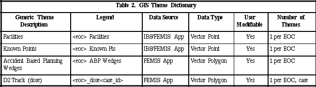
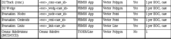
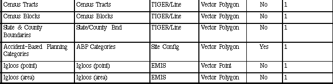
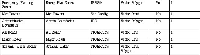
Table 2 lists the FEMIS spatial themes along with their data sources and other
characteristics. The FEMIS themes can be divided into four categories:
1. Static themes are background map layers and other themes that change infrequently
and are managed and controlled by the system administrator at the FEMIS site. Users
are not permitted to modify the spatial or attribute information contained in these
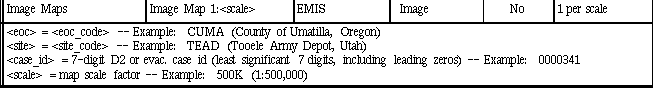
datasets. Examples of static themes are roads, census blocks, and image maps. All of
these themes are pre-loaded into the FEMIS spatial database.
2. Themes with user-modifiable attributes are themes with attributes that can be
modified by users from within certain FEMIS modules. Updates are restricted to the
temporary addition or modification of designated attributes of existing theme
features. The emergency planning zones theme is an example of a theme with
user-modifiable attributes. The operator/planner can insert or modify a protective
action recommendation or decision status (evacuation or sheltering) for each
emergency zone within the risk area.
3. Themes with user-added features are existing themes which allow users of FEMIS to
add new geographic features. These themes are currently restricted to point (event)
themes and include facilities and other known points. The facilities theme is initially
loaded with the locations of buildings and other facilities of interest for emergency
planning purposes. Users can then add other facilities to this theme. Known points
are other locations that users may wish to include as named reference points, such as
the location of a hypothetical or real emergency event, or potential traffic control
points during the evacuation of an area.
4. Model-generated themes are created by applications that are linked to the hazard
dispersion and evacuation models. A separate theme is created and stored on the
user's PC for each model case that is run. Because these themes are generated
dynamically in response to calls from the FEMIS application software, they are not
loaded initially.
5.2 Data Sources and Import Processing
ArcInfo is used to process the raw spatial data and convert it into ArcView themes.
Associated attribute data must also be prepared for loading into the FEMIS relational
database. The five primary sources of FEMIS spatial data are listed below.
1. IBS (Integrated Baseline System)[PNL2] IBS was developed by Pacific Northwest
Laboratory (PNL) for the U.S. Army as an interim off-post emergency management
system. IBS stores and manages spatial data and related attributes of off-post
geographic features and modeling results.
2. EMIS (Emergency Management Information System)[ACS] EMIS was developed by
Applied Computer Systems, Inc., for the U.S. Army as an interim on-post emergency
management system. EMIS stores and manages spatial data and related attributes for
on-post geographic features, modeling results, and raster image background maps of
the area surrounding the CSEPP site.
3. TIGER/Line Data The U.S. Bureau of the Census provides TIGER/Line data files
that contain location and attribute information for a variety of physical and
non-physical features such as roads, railroads, streams and water bodies, landmarks,
state and county boundaries, and census unit boundaries.
4. Site Configuration Data Some spatial data related to planning decisions made at the
site (e.g., accident-based planning category boundaries) may not be available from
any other existing data system. This data must be obtained directly from site
personnel and must be entered into ASCII files or digitized from Unites States
Geological Survey (USGS) maps or other printed maps prior to FEMIS import
processing.
5. FEMIS Application Models The FEMIS application uses the model outputs from the
dispersion and evacuation models to generate ArcView themes via calls to Avenue
scripts.
6.0 Implementation Issues
One of the major challenges in building FEMIS was to integrate the commercial software
packages with the FEMIS application in such a way that the entire system has a reasonably
consistent "look and feel" as a single integrated product. ArcView provides limited
flexibility in the positioning and appearance of the user interface. In addition, Arcview
does not use standard Open Database Connectivity (ODBC) drivers to access the Oracle
relational database. To compensate for these limitations, we built a shell of Visual Basic
around ArcView to access the database and handle most of the user dialogue. This Visual
Basic shell facilitated the customization of the user dialogue to present a "look and feel"
that is similar to the remainder of the FEMIS application.
Other specific issues and problems encountered in using ArcView to implement the GIS
subsystem of FEMIS are described in the following paragraphs.
6.1 GIS Application Interface
All GIS interactions with the FEMIS application are performed through DDE calls to
ArcView, in which ArcView is the server and the FEMIS application is the client. All
DDE calls pass to ArcView the name of the script to be executed and a parameter list. The
first three parameters are always the name of the FEMIS executable application that makes
the DDE call, the link topic, and the link item. These parameters are used to create a DDE
client to send back the results from the ArcView script execution. The remaining
parameters are used as inputs to the ArcView script to be executed.
One limiting factor of this approach is the maximum length of the parameter string in the
DDE call (currently 255 characters), a DOS limitation. This limitation, encountered in
spatial analysis requests, in polygon creation, and in animation, was circumvented by
storing the actual parameter string in a file and passing the file name in the DDE call.
Given the choice, we would have preferred a more robust and efficient interprocess
communication mechanism such as that provided by an application programming interface
using DLL. However, ArcView does not currently support a DLL interface.
6.2 Feature Attributes and Display Characteristics
Attributes of features contained in FEMIS themes are currently stored as columns in the
ArcView theme table. Some of the themes also have attributes that are stored and
managed in the relational database. If a change is made to a theme's feature locations or
attributes within the relational database, the change is communicated to ArcView through
a DDE message to initiate modification or regeneration of the ArcView theme.
Display characteristics of a theme are currently loaded from legend files or initialized
during the setup process based on parameters in an initialization file. In future FEMIS
releases, these characteristics will be stored in GIS data dictionary tables in the FDB. The
GIS data dictionary will define default display characteristics (legend parameters) for each
theme. It will also permit the definition of optional display characteristics based on
attribute classification.
6.3 Set-up and Configuration Management
ArcView provides a development environment in which the script editor is integrated with
the graphical user interface (GUI). The ArcView project file is a snapshot of the ArcView
system as of the moment the project is saved. The project status, as represented by the
ArcView GUI, scripts (Avenue code), views, charts, tables, and associated data pointers, is
captured in a project file characterized by the ".apr" extension. When the project is started
again, it presents the user with the same environment as of the moment the project was
saved.
The project file is a powerful development vehicle. It allows the developer to write new
scripts, compile them, and execute them without having to re-compile and re-link the
existing scripts or modify the GUI. However, there are some drawbacks: 1) the data are
not separate from the code, 2) the same GUI is presented to all users, and 3) code
configuration management is difficult. The following paragraphs describe some of the
steps that were taken to minimize these problems.
6.3.1 Separation of Data from Code (Data Independence)
FEMIS is intended to be used in a number of geographically disparate locations with
different data characteristics and requirements. The same code must be applicable to all of
the spatial datasets. Although it would be easy for a user to enter ArcView and add or
delete datasets (themes), it is not obvious how this should be done to ensure that the GIS
code will operate properly and consistently on the specific set of themes that are included
in the project. Our solution to this problem was to store appropriate metadata (theme
names, legend parameters, and other descriptive information) in the FDB for all of the
site-specific spatial datasets. As part of the on-site installation, the spatial metadata for
the site are accessed from the relational database, and the relevant themes are loaded into
the project under control of an Avenue script, as specified by the information in the
metadata. The ArcView GUI is then customized for FEMIS use; the project file, with its
pre-loaded themes and Avenue code, is stored; and the project is then ready for use by the
FEMIS application.
6.3.2 GUI Regeneration
The FEMIS requirements for simplicity of use and minimal training created the need for a
simplified ArcView graphical user interface. A simplified interface is less confusing to
first-time users, but it imposes restrictions on the expert user or developer. Therefore,
ArcView scripts were written to modify the default ArcView GUI to meet the FEMIS
requirements, and to optionally restore the full GUI for the expert user or developer. The
usual cloning of a GUI was not adequate here because a GUI is tied to a document, and
FEMIS requires the same interface for all documents of the same type (e.g., all tables
should be presented with the same GUI).
6.3.3 Configuration Management
Developing code within an ArcView project has at least two risks: 1) a code error may
corrupt and destroy the entire project file; and 2) a second developer may be in the process
of making some changes that are incompatible with the first developer's modifications.
Storing the project file in a code control system does not help because if one developer
needs to modify a script, he has to check out the entire project file, and this prevents other
developers from working with any of the code components contained in the project. Both
problems are due to the fact that the project file contains both the source code and the
"executable" software. To solve these problems without losing the advantages of the
project file, we automated a script back-up and restore process that allows the project file
to be rebuilt from the text files of the scripts. If the script text files are saved in a code
control system, they can be checked out with the proper locks that would let fellow
developers know that a specific script is being worked on by another person. Furthermore,
the script text files can now be archived for each major code release and treated as
traditional code.
7.0 Conclusions and Lessons Learned
ArcView proved to be a dynamic and flexible environment for implementing the required
GIS functionality for FEMIS. This environment and the object orientation of Avenue,
ArcView's scripting language, allowed rapid prototyping and implementation and helped
to make the development process enjoyable. A more versatile debugger could have made
the process even more productive and enjoyable.
The most significant limitations encountered were
- the inability of ArcView to use the standard Microsoft ODBC drivers to access the
Oracle database. The drivers made by Q&E and recommended by Esri for use with
ArcView were not compatible with some aspects of the Visual Basic code used in the
FEMIS application. This inadequacy made it impossible to access the FDB directly
from ArcView.
- the lack of a robust inter-process communication mechanism such as that provided
by an application programming interface (API) using DLL.
- the limited ability of ArcView to customize the user interaction dialogue and style. It
was thus difficult to make the ArcView dialogue appear similar to that used in the
remainder of the FEMIS application.
To compensate for these limitations, we built a shell of Visual Basic around ArcView to
access the relational database and handle most of the user dialogue. This helped to make
the user interface more uniform throughout the FEMIS application. In retrospect, building
the Visual Basic shell was a fortunate decision because there will be very little
reprogramming required to convert the ArcView DDE calls to DLL calls when future
ArcView releases provide for the integration of DLLs.
Acknowledgements
FEMIS is the product of the FEMIS project team. Many members of this team provided
comments and suggestions that helped to make this a better paper. The contributions of J.
Bower, M. Burford, T. Coonelly, T. Downing, D. Millard, and J. Williams are especially
appreciated.
References
[PNL1] Pacific Northwest Laboratory. System Design Description, Federal Emergency
Management Information System, Phase I, Version 1.1. Richland, Washington, March
1994.
[ORNL] Oak Ridge National Laboratory, Center for Transportation Analysis. User
Manual for OREMS: Oak Ridge Evacuation Modeling System, Version 1.0. Oak Ridge,
Tennessee, 1994.
[IEM] Innovative Emergency Management, Inc., and M. Myirski. Reference Manual:
D2PC and Hazard Analysis. IEM, Inc, Baton Rouge, Louisiana, August 1993.
[PNL2] Pacific Northwest Laboratory. Integrated Baseline System (IBS), Version 2.0
User's Guide. Richland, Washington, March 1994.
[ACS] Applied Computing Systems. User Documentation for the U.S. Army
Emergency Management Information System, EMIS Version 2.04. Los Alamos, New
Mexico, February 1994.
1 This work was supported by the Chemical Stockpile Emergency Preparedness Program
(CSEPP) Office, U.S. Army Chemical and Biological Defense Command, under a Related
Services Agreement with the U.S. Department of Energy (DOE). Pacific Northwest
Laboratory (PNL) is operated for the U.S. Department of Energy by Battelle Memorial
Institute under Contract DE-AC06-76RLO 1830.
2 Avenue is the programming language of ArcView.
3 Key words in italics indicate actual FEMIS button labels or menu items.