Daene
C. McKinney Ximing Cai David R. Maidment
A Prototype GIS-Based Decision Support
System
for River Basin Management
Abstraction
This paper presents
a prototype spatial decision support system (SDSS), which is a conjunctive
application of GIS and DSS technologies, for river basin water resources
planning and management. In this GIS-based DSS, a river basin is modeled
as a collection of spatial objects which represent the river basin physical
entities, and thematic objects. The thematic objects represent a river
basin network, attributes for river basin entities, physical laws that
govern the spatial objects in the real world, and the socio-economical
policies that control the operation of the river basin (we define the laws
and policies as relation objects), and inquiring schemes in which the network,
attribute, and relation objects are connected under user interactions (we
define the schemes as model objects). Therefore we use an object-oriented
approach to integrate a river basin visual representation and logical representations
of a river basin into an operational framework. Several object-oriented
functions are developed, which include data input/update, network derivation,
network modification, model generation, system connection, visual display,
and the user interface. The system operation procedures are also discussed.
Introduction
Geographic information
system (GIS) based decision support systems (DSS), often known as spatial
decision support systems (SDSS), are a class of computer systems in which
the technologies of both GIS and DSS are applied to aid decision makers
with problems that have a spatial dimension (Walsh, 1992). GIS is a general-purpose
technology for handling geographic data in digital form, with the ability
to preprocess data into a form suitable for analysis, to support analysis
and modeling directly and to postprocess of results (Goodchild, 1993).
GISs offer a spatial representation of water resource systems, but currently
little predictive and related analytical capacities are available for solving
complex water resource planning and management problems (Walsh, 1992; Parks
1993). DSSs are interactive programs, often with a graphical user interface
(GUI), which embed traditional water resource simulation and optimization
models, with adaptation of new approaches, to support users in semi-structural
or ill-structural problem solving (Loucks and daCosta 1991). An extension
of the DSS concept, a spatial decision support system (SDSS), which is
the integration of DSS and GIS, was initiated by Densham and Goodchild
(1989), and the research potential for SDSS in water resources was addressed
by Walsh (1992). SDSSs integrate the spatial dimension and modeling capacity
into an operational framework, so that DSS and GIS technology can both
be more robust by their linkage and coevolution.
In this
paper we consider a DSS for water management in river basins. That is to
say, the DSS focuses on a specific rather than a generic problem, and provides
aid for decision makers in river basin planning and management, rather
than general users. The specific DSS is developed in the environment of
a general-purpose GIS, and we call it the GIS-based DSS for river basin
management.
River basin
management, considered at the spatial scale of a river basin, is treated
as a kind of decision analysis based on the physical conditions of the
river basin and the socio-economic conditions in the basin. A river basin
system includes three components (1) source components such as rivers,
canals, reservoirs, and aquifers, and (2) demand components such as irrigation
fields, industrial plants, and cities, and (3) intermediate components
such as treatment plants, and water reuse and recycling facilities. A river
basin system is made up of these components and the relations between them.
To construct a model for river basin management, generally we often model
it as a node-link network from the river basin map, with nodes representing
lakes, reservoirs, and aquifers, whose length dimensions may be insignificant,
and links representing rivers, canals, whose lengths are significant. (Loucks,
1996). In this paper we set up a network configuration, which is different
from that of the traditional node-link network. In the network defined
here, nodes represent all source, demand and intermediate components, no
matter whether the length dimension of a component is significant or not.
For example, a river is divided into a number of reaches, and each reach
is represented as a node; while links in the network represent the spatial
relations between two components. There are two kinds of links, one are
the natural links, for example, a link between two consecutive river nodes;
and the other are man-made links, which represent the water supply-demand
relations, for example, a link between a reservoir node and a demand site
node. Therefore, links in the network are abstract objects, which only
represent one node linked to another node.
Both GISs and
DSSs have been widely used in water resources, and SDSSs, as the conjunctive
use of GISs and DSSs, have also been contributed to our understanding of
water resources in recent years. Both GISs and DSSs have been widely used
in water resources, and SDSSs, as the conjunctive use of GISs and DSSs,
have also been contributed to our understanding of water resources in recent
years.Compared to traditional DSSs, SDSSs have been improved through the
incorporation of GIS in the aspects of data base, interface and model connection,
etc. For data base, a GIS not only brings spatial dimensions into the traditional
water resource data base, but also, more significantly, has the ability
to integrate various social, economic and environmental factors related
to water resources planning and management for use in a decision-making
process. Therefore such a system helps to attain an integrated view of
the world.(Lam and Swayne,1991; Cowan et al.,1996). For interface, the
visual display capacity of GISs and the graphical user interface of DSSs
complicates the user interface of a SDSS, which allows the user to take
complete control of data input and manipulation. The sophisticated user
interfaces can provide user-defined triggers, which allow the user to dictate
how features will respond to environmental changes, and to construct rules
to control the modeling process (Crosbie,1996). The ease and flexibility
in which any water resource system can be defined, modified and visualized
through the designed interface should bring ease and flexibility to the
modeling and result analysis (Loucks et al.,1996).
The coupling of environmental
models with a GIS is the major issue in a spatail decision support system
(SDSS). For water resources problem solving, both the spatial representation
of water resource systems and the insight into water resource problems
are necessary (Walsh, 1992). GISs have been applied to provide the former,
water resource models provide the later, and SDSSs provide the integration
of both. There are several strategies and approaches for the coupling of
environmental models with a GIS (Nyerges, 1993; Fedra, 1996), which can
range from loose to tight coupling. A loose coupling is just the transfer
of data between models and GIS, and it is based on two separate systems
and generally separate data management. A tight coupling is one with integrated
data management, in which GIS and models share the same database. The tightest
of couplings is an embedded or integrated system, in which modeling and
data are embedded in a single manipulation framework (Crosbie, 1996, Fedra,
1996; Fedra and Kubat, 1993, Djokic and Maidment, 1993, McKinney et. al.
1993, Burgin, 1995, etc.)
Object orientation
as an integrated approach seems to be very promising for deep coupling
of GIS and environmental models (Fedra, 1996; Crosbie 1996; Raper and Livingstone
1996; Densham and Goodchild 1990;) The idea beyond this approach is that
the world is perceived as consisting of objects that interact in specific
ways (Crosbie,1996). Object-oriented representation of the world includes
spatial objects and thematic objects. Spatial objects represent real world
entities, and thematic objects include attributes, methods, and topics.
Beside the spatial attributes that can be directly derived from a GIS,
there are external physical, environmental and socio-economic information
related to the spatial entities. Methods are rule sets or functions defined
for description or exploration of the relationships over the spatial objects.
Topics represent tasks or objectives to be completed or reached, which
is often identified through user interactions. Based on the given attributes,
models and GIS functions are understood as methods for topics, and the
integration of models and GIS functions becomes the pragmatic question
of which method can perform the required task on the selected objects (Fedra,
1996). Several applications on object-oriented SDSS have appeared in water
resources literature (Reitsma 1996; Fedra and Jamieson, 1996; Loucks et
al. 1995 etc.).
In this paper
we present a prototype spatial decision support system for water resource
allocation in river basins. A river basin is represented as spatial objects
and thematic objects in a GIS. Several object-oriented GIS functions are
developed, which include (1) Data input/update, manipulating thematic objects
for data preparation; (2) Network derivation, automatically deriving an
abstract river basin network from a river basin map, based on the spatial
relationships within the real world represented by the map; and (3) Network
modification, for users to modify the network and build the representation
they prefer, and users can also use this tool to draw a network based on
the river basin image in raster format, and (4) Model generation, automatically
generating a water resource allocation model through interactions with
users, and (5) System connection, allowing the SDSS to call any external
programs, and (6) Visual display. All these functions are built into a
graphic user interface. The data, models and all operations are integrated
in a GIS environment (ARCVIEW), and this GIS-based decision support system
can support multiple objective analysis for river basin management issues,
like water resources allocation in the river basin.
In the rest of
this paper, a detail introduction of the modeling system is presented.
A case study for the Kashkadarya River basin in Central Asia is given.
Emphasis will be given to the aspects of using database, interface and
GIS in modeling techniques.
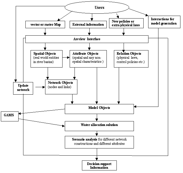
System Design - General Introduction
The idea
for the system design is to put the data, the model and the decision analysis
process all together into the environment of the GIS. The GIS we use is
Arcview, a GIS software package with a high-level object-oriented programming
language, namely, Avenue. Figure 1 shows the structure of the GIS-based
DSS. A river basin is represented by spatial objects, which represents
the real world entities, thematic objects which include the network, attributes,
logical and policy relations, and models. A mathematical programming model
is generated based on the network, attributes, physical laws and control
policies, and users' interaction. Currently the SDSS can generate two models.
One is a linear optimization model for water resources allocation in a
river basin without considering water quality, the other is non-linear
optimization model with both water flow balance and salt balance. Other
models, like economic models for river basin management are under development.
For some models, like the optimization models for water allocation in a
river basin, an external solver is needed. In our case, we use GAMS (General
Algebraic Modeling System), to solve the optimization models. The system
writes the model in the GAMS language. When the model is ready, The optimization
solver GAMS is called to run in a window within GIS Arcview, and the results
from GAMS are read into Arcview data base.
The GIS-based
DSS is designed as an adaptive system, which can evolve as new spatial
objects, and thematic objects including attributes, logical and policy
relations, and models, and can also adapt user-defined operating rules
or user-preferred changes are modified, added to, or deleted from the system.
This adaptive ability makes the system general to water management problems
in any river basin.
Since all
operations are done within the GIS, all the primary functions of the GIS
are available to users, and all the new functions, which are not in the
current GIS, are developed in the object-oriented programming language
of the GIS, namely Avenue, and they are embedded in the same interface
as the primary GIS functions.
Figure 1 Structure of the SDSS
Representation of A River Basin
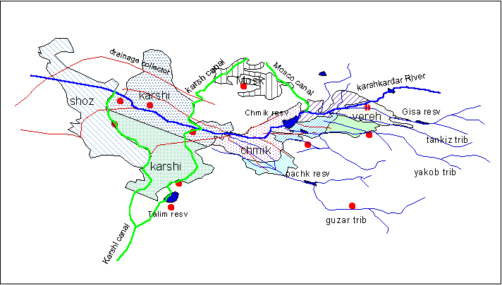
The river
basin used for a case study in this paper is the Kashkadarya River basin,
which is a sub-basin of the Amudarya River basin in the Aral Sea region
of Central Asia. Figure 2 shows a digitized map of the basin. A major canal,
the Mosco canal, diverts water from the Kashkadarya River to a region outside
of the basin, namely Mosk. Since the local water in the basin is not sufficient
for water supply, another major canal (Karshi Canal) diverts water from
the Amudarya River to the Kashkadarya River basin. There are several reservoirs
in this basin, and the major ones include the Chmik Reservoir on the Kashkadarya
River, and the Talim reservoir on the Kashi Canal. The reservoirs have
enough capacity to control the normal natural inflow and diversion from
the Amudarya River (McKinney and Karimov, 1997). Although the water demand
is mainly supplied by surface water, groundwater in several aquifers in
this basin plays an important role in water supply. There is intensive
irrigated agiculture in this basin, and irrigation water occupies the major
part of the total water demand in this basin. Figure 2 shows 8 demand sites,
which are delineated based on the administrative districts and irrigation
field distribution. For these demand sites, beside the water supply canals,
there are collector canals that collect drainage from the irrigation fields
and send it back to reservoirs, rivers or aquifers.
The natural semi-arid
climate and the intensive irrigation create two typical problems in this
basin: water quantity shortage and salinization. Our primary research purpose
is to develop an efficient water allocation tool to aid in the resolution
of the problems in this basin.
Spatial Objects
For our study purpose, the required spatial
items in the river basin include (Figure 2):
1.the main river, divided into reaches,
2.the tributaries and canals which divert
water to the river basin,
3.the canals, which divert water from
the main river to demand sites,
4.the collector canals, which collect
agricultural drainage or other return flows from demand sites,
5.the reservoirs and lakes,
6.the groundwater sources (aquifers),
7.the demand sites, which include cities
and irrigation districts or fields,
8.water treatment plants,
9.hydropower stations, and
10. administrative districts or regions.
To input these
entities into the GIS-based DSS, one can digitize river basin maps using
the GIS's digitizing capacity . An alternative way is to read the river
basin image files in raster format into the GIS, but some of the system
functions, like network derivation, does not work in this way.
Figure 2 A river basin map (the Karshikardaya River basin
in Central Asia)
We define
each of these entities as a spatial object, and we can use them to make
any required spatial analysis, but generally, a mathematical model, which
is an abstraction of the real world can not be built directly on real world
maps. To overcome this obstacle, we will introduce thematic objects in
the following.
Thematic Objects
We
can use the GIS to extract a river basin network from the real world representation,
and then the network becomes a bridge between the real world and mathematical
models. In the river basin network, the spatial objects are treated as
nodes, and the spatial relations between the objects are treated as directed
arcs or links. In the river basin map, we see the spatial relations between
two spatial objects, for example, a tributary intersects with a demand
site; while in the network view, we see a link (line) between them, which
means the tributary may supply water to the demand site. Figure 3 shows
a network for the case study river basin.
Each of
the nodes and links in the river basin network is defined as a thematic
object. The node objects inherit spatial characteristics from the corresponding
spatial objects. This inheritance will be addressed later in the discussion
of network derivation functions. However, the link objects do not have
any digital spatial characteristics, and they only specify "which
node is linked to which other node". The links defined in a river
basin network are listed in Table 1.
Table 1 Links in a river basin
network
Name Description
rilink links between river nodes
ri_rev links from river nodes to
reservoir nodes
ri_cal links from river nodes to
canal nodes
ri_dm links from river nodes to
demand nodes
nglink links from river nodes to
aquifer nodes
rev_ri links from reservoir nodes
to river nodes
rglink links from reservoir nodes
to aquifer nodes
rev_dm links from reservoir nodes
to demand site nodes
rev_rev links from reservoir nodes
to reservoir nodes
cal_dm links from canal nodes to
demand site nodes
cal_rev links from canal nodes
to reservoir nodes
c-glink links from canal nodes
to aquifer nodes
dm_drn links from demand site nodes
to collector nodes
dtlink links from demand site nodes
to treatment plant nodes
drn_ri links from collector nodes
to river nodes
drn_rev links from collector nodes
to reservoir nodes
gw_dm links from aquifer nodes
to demand nodes
tnlink links from treatment plant
nodes to main river nodes
trlink links from treatment plant
nodes to reservoir nodes
rplink links between reservoir
nodes and power station nodes
nplink links between river nodes
and power station nodes.
Corresponding
to each node object in the network, there are two sets of attributes, one
is the spatial characteristics, like coordinates, length for lines, and
area and perimeter for polygons, etc., and this set of attributes can be
derived by the GIS directly; the other is any external information which
has spatial characteristics, including additional physical information
and social, economic and environmental information, and these attributes
are available from related external sources and they should be input into
the GIS. For example, for a reservoir object, the spatial characteristics
include the reservoir's area, perimeter, and the coordinates of the reservoir
area's center. The external information for a reservoir includes the reservoir
topographic relations (e.g., elevation vs. area, elevation vs. volume),
reservoir inflow and pollution load, average water temperature in different
seasons, and some parameters related to reservoir operation for water supply,
electric power generation, water release for ecological and environmental
purpose, and flood control. Link objects, which specify "which is
linked to which", do not have any spatial characteristics, but there
is some external information associated with them. For example, for a link
from an aquifer to a demand site, pumping capacity and maximum allowed
pumping are necessary information for the link.
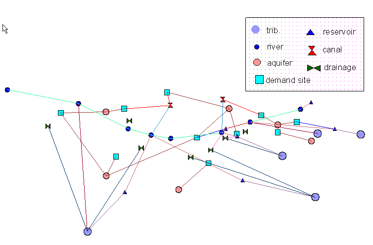
Figure 3 A demonstration of network(part of links) for the Karshikardaya
River basin.
In the GIS, the
attributes of a node or link object are stored in tables. For each node
or link object, there is such an attribute table. In the GIS-based DSS,
the attribute tables are also defined as thematic objects, subordinate
to the node and link objects in the network.
We define another
class of thematic objects to describe the physical laws that govern the
spatial objects in the real world, and the socio-economic policies that
control the operation of the river basin system. The network objects (node
and link objects) should also obey these laws and policies. For example,
water balance and salt mass balance for a reservoir node, or operation
rules for a reservoir. This class of thematic objects represent advanced
relations between each network object and any other related network objects.
We name these objects relation objects.
Finally, models
for river basin analysis are defined as a class of thematic objects, which
represent a set of inquiring schemes in which the network objects (node
and link objects), attribute objects, and relation objects are specified
by the user interactions. We will illustrate how to construct the model
objects in the following discussion on model generation function.
Through this
system, a river basin is visually represented by spatial objects, and is
logically represented by thematic objects. Visual representation allows
users to see what the river basin looks like, while logical representation,
which is logically and mathematically operational for users, provides a
window for users to see what happens or what will happen in the river basin
under various scenarios. This is what allows us to perform optimization
or simulation, a logical program on the system to evaluate and control
the system performance.
Models for Water Allocation in a River Basin
Before we go
further to discuss the functions of the GIS-based DSS, we discuss the models
applied for water allocation decision analysis in a river basin. Currently
we just consider optimization models. A multiple objective analysis (MOA)
approach is used in the optimization models to deal with the complexity
of water allocation involving multiple purposes.
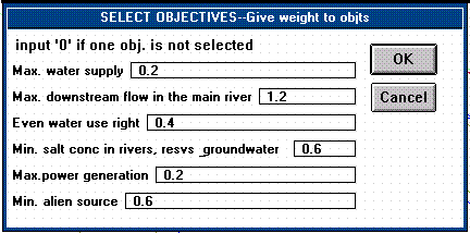
Objectives
The optimization
models may include multiple objectives, such as
-
Maximize the satisfaction of water
demand at demand sites;
-
Minimize the differences of water
shortage among the demand sites.
-
Maximize the downstream flow in the
main river;
-
Minimize the salt concentration in
the water system;
-
Maximize the satisfaction of hydropower
power generation demand; and
-
Minimize the water amount diverted
from other basins.
Users can select one or more, or all,
of the above objectives. By specifying different objective weights, multiple
objective analysis can be performed and tradeoffs between those objectives
can be evaluated (McKinney and Cai, 1996).
Constraints
There are three
kinds of constraints: physical constraints (e.g., mass balances), policy
constraints (e.g., upper and lower bounds on variables), and system control
constraints (e.g., to maintain feasibility). The physical constraints result
from by the model generation function directly, based on the river basin
network. The generation of policy and system control constraints requires
user interactions.
The physical
constraints are the major part of the model constraints. The concept of
this kind of constraint is a mass balance, including water mass balance
and salt mass balance in rivers and tributaries, reservoirs and lakes,
aquifers and demand sites. Water flow and salt transport in the system
are described by the mass balance equations. The physical constraints also
include some physical limits, such as river and canal diversion capacity,
groundwater pumping capacity, hydropower power generation capacity, and
waste water treatment plant capacity.
The policy constraints
are specified by setting upper and lower bounds of variables. For example,
the water diversion from a reservoir to a demand site may not be allowed
to exceed a given amount and the system control constraints are used to
maintain feasibility of the model solution, and they are also used to control
the model performance, e.g., making the solution more stable or more realistic.
Currently, the
optimization models developed here include a linear model and a non-linear
model. The linear model considers the water quantity balance, and the non-linear
model can conjunctively consider water and salt mass balance, and it can
also consider the non-linear power generation equations.
Object-Oriented Functions
Data Input/Update
On a graphical
screen showing the river basin network, the data input/update functions
allow users to click any node or link object, and then a tabular window
is opened for users to input/update external information for the node or
link object that they selected. The experienced GIS users can use the attribute
input methods to directly edit the attribute tables in the GIS.
Network Derivation
To write a mathematical
model for the simulation or optimization of a river basin , one starts
by extracting the system network from river basin maps, and traditionally
this work is done by hand. The network deriving tool can automatically
derive the abstracted river basin network from a river basin map, based
on spatial relationships within the real world;
In the GIS ,
several spatial relations can be used to resolve problems related to location,
such as proximity, adjacency, and containment. Those spatial relations
are defined for a selected spatial object, the one doing the selecting,
and a target spatial object, the one from which items are being selected.
First, the network derivation tool searches all spatial objects, identifies
them as nodes in the network, and transfers the spatial attributes from
the spatial objects (parent objects) to the nodes; second, the tool searches
all spatial relations between the spatial objects, and identifies them
as links in the network, and finally, all nodes and links are defined as
thematic objects and are displayed in a view. Figure 4 shows a simplified
example for deriving a network.
The spatial relation
functions that Arcview provides include:
Are Completely Within - selects
features in the target themes if they fall completely within one or more
of the selector theme's features;
Completely Contain - selects features
in the target themes that completely contain one or more of the selector
theme's features;
Have their Center In - selects features
in the target themes if their center falls inside the selector theme's
features;
Contain the Center Of - selects features
in the target themes that contain the center of one or more of the selector
theme's features;
Intersect - selects features in the target themes that intersect the features
in the target. Intersection implies that at least one point is common to
both the selector and the target or one of them is
completely within the other. If the selector and target are the same, Intersect
will select adjacent features; and
Are Within Distance Of - selects features in the target themes that are
within a specified distance of the selector theme's features. We can specify
the type of distance units in the View Properties dialog
box.
We incorporate
all these spatial relation functions into an Avenue program, which can
be used to search and identify every kind of spatial relations in a coverage,
and represent those relations as corresponding links in a network. For
some cases, the system can specify the links quantitatively. For example,
considering the links from a demand site to aquifers, because one demand
site may spatially intersect with more that one aquifer. To measure the
potions that the demand site overlays different aquifers, a grid coverage
is designed, and the system identifies the common grids that the demand
site and each of the aquifers, and then calculate the intersected areas
by the number of the grids and the grid size.
If the
river basin map is input as a raster image file, then the network deriving
tool will not work, and users need to draw the network according to entities
shown in the image by using the network modifying tool, which is introduced
below.
Network Modification
The network
deriving function identifies links only by spatial relations, such as proximity,
adjacency, and containment. For some cases, the links may not exist in
the real world. For example, if a tributary intersects a demand site on
the map, the network deriving tool will define a link from the tributary
to the demand site, which means the tributary supplies water to the demand
site. However in the real world, this supply may not exist because of some
physical, social and political limits. For another case, Since the river
basin map may only represent the current conditions, and user may want
to plan some changes to the system, the network deriving tool will not
define network nodes and links for the variants since they may not exist
in the original map. In these cases, it is necessary for the user to use
a tool to modify or update the network for this purpose. The network modify
tool allows users add (delete) new (existing) nodes or links to build a
variant network. The tool is designed as a user-defined trigger (Crosbie,
1996), by which users can build the model construction to suit their interests.
When an existing node or link is deleted, the attributes associated with
it will be made inactive; while when a new node or link is added, a window
prompt will allow the user to input any required external information.
Model Generation
As mentioned
in the river basin representation section, models for river basin analysis
are also defined as a class of thematic objects. The generation of this
class of thematic objects is shown in Figure 5. The model generation function
generates the GAMS codes for the optimization model. The generating process
involves user interactions, such as selecting the model type (linear or
nonlinear), specifying initial conditions and targets for objectives, setting
preferences (weights) for the objectives, and setting policy control constraints.
The model
objects inherit characteristics from network objects, attribute objects
and relation objects, and they are also affected by user interactions.
Therefore, the model objects represent variants for any change in the network
configuration, input data, control policies, or user interactions.
The spatial
objects, i.e. the node in the network, are the central objects in the model
generation function. They are classified into classes corresponding to
the physical entities, including reservoirs, river reaches, tributaries,
aquifers, canals, treatment plants, and demand sites. The model generation
function takes action on each member in each of these classes. The procedures
for the model generation function are illustrated in the following table.
Table 2 Procedures for the model
generation function
Identify the model type
Identify the objectives
Define the studying epochs
Define the decision variables
Identify the initial values
for some variables
Identify the objective weights,
if multi-objectives are identified
Generate the objective equation
For each class of spatial
objects :
For each member in the current class :
Search the subordinate attribute
objects
Search the subordinate link objects
Interact with the relation objects
(physical laws and control policies)
Generate the constraint equations
End for one class of the spatial objects
End for all classes of the spatial objects
Taking reservoirs as an example, Table
2 shows the details for the actions that the model generation function
puts on the spatial objects.
Table 3 Example for generating
model components related to reservoirs
For each reservoir in the reservoir class
:
Search the subordinate attribute
objects
{ reservoir storage capacity, topologic
relation between storage and surface area, and between
storage and elevation, evaporation coefficient
(volume per unit of surface area), seapage
coefficient (percentage of storage), salt
loading, hydropower generation capacity and efficiency,
initial storage and salt concentration
etc. }
Search the subordinate link objects
{ link from a river reach to the reservoir,
link from a tributary to the reservoir,
link from a source canal to the reservoir,
link from a collector canal to the reservoir,
link from a treatment plant to the reservoir,
link from a upstream reservoir to the
reservoir,
link from the reservoir to a river reach,
link from the reservoir to a tributary
,
link from the reservoir to a aquifer ,
link from the reservoir to a treatment
plant,
link from the reservoir to a downstream
reservoir,
link from the reservoir to a demand site,
for the case where diversion canals are ignorant, and
link from the reservoir to a canal, only
for those major canals }
Interact with the relation objects
(physical laws and control policies)
{ flow mass balance ,
salt mass balance,
hydro-electric power generation equation,
and capacity limit
release control policies,
power demand target, and,
salt concentration limit, etc. }
Generate the constraint equations
End for the reservoir class.
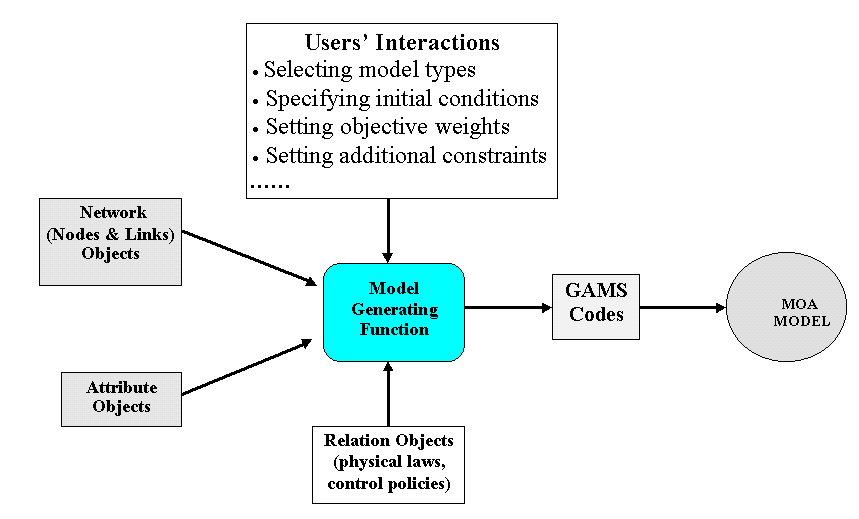
Figure 5 Model generation process in the SDSS
System Connection
In the SDSS prototype
developed here, a commercial optimization package, GAMS, is used to solve
the models. The system connection function can call GAMS from within Arcview.
When the GAMS codes for the optimization model is prepared by the model
generation function, the system connection function calls GAMS, and within
Arcview a window is opened to show GAMS solving information. When GAMS
completes execution, the system connection function writes the solution
into the attribute objects.
Visual Display
Besides the primary
display capacity of the GIS , an enhanced display function can display
error, help or progress information during the execution of all the functions
described above; and it can display primary data or modeling result in
tables or charts, for each network (node and link) object that the user
selects.
User Interface
Since the prototype SDSS
is designed within GIS Arcview, and the interface of Arcview is available
to users. New interface is customized by using Avenue for the specific
purposes of the prototype SDSS. Through the new interface, a user can easily
conduct the functions described above, including data input or update,
network derivation and modification, model construction and operation,
and result display. The interface provides help information such as step
by step procedures, options for some alternatives such as model types and
initial condition for modeling, and visual view of modeling processes.
Various graphics, message boxes, menus, and windows provide friendly interface
to users.
The interface is especially
significant for model construction process. As described in model generation,
the model construction process involves the interactions between users
and the SDSS. River basin management models are made up not only by physical
and socio-economic issues, but also by some individual decision preference.
During the model construction process, the SDSS asks a user some questions,
or prompts to him some options. The user's answers to the questions or
choices to the options are incorporated into the model. For example, the
SDSS may ask the user if he wants to set a goal for the salt concentration
in the downstream flow, or set a limit for pumping from a aquifer; if the
user chooses multiple objectives for the river basin management, then he
will be asked to specify a weight for every objective. The interface designed
in the SDSS provides a dialogue environment between the system and users.
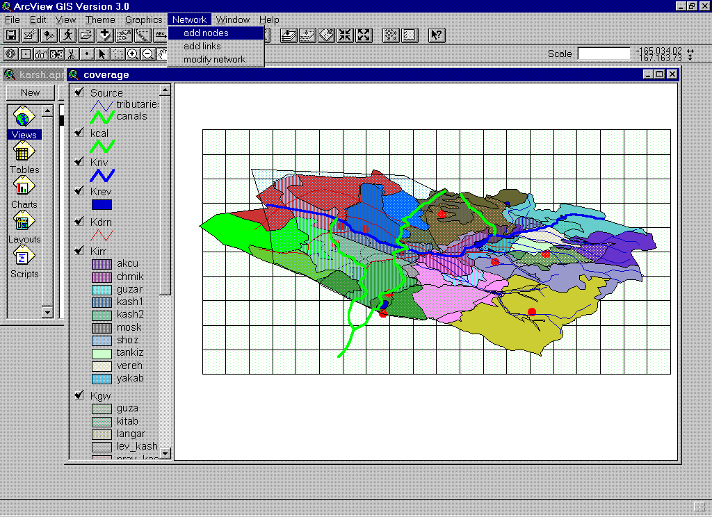
SDSS Operation Procedures
1. Activate ARCVIEW, and open the project
for the SDSS. Figure 6 shows the menus, tools, and buttons designed for
the SDSS.
Figure 6 Menus, tools and buttons
2. load
a river basin geographic themes into a map view. The geographic themes
respectively represent rivers, canals, reservoirs and lakes, aquifers and
recharge zones, treatment plants, irrigation fields, and towns and cities,
etc.
3. Create
a network from the geographic themes in two steps: adding nodes and adding
links. First the SDSS searches each kind of nodes corresponding the geographic
themes and add these nodes into a network view. Secondly, the SDSS examines
the spatial relationships between the geographic themes, identify links
based on the spatial relationships, and add these links into a network
view. Figure 3 shows an example for a map view and a network view.
4. Modify the
network There are several tools for users to modify a network, which include
"add nodes tool", "add links tool", and "delete
nodes/links tool". To add a node, a user first click a point in the
network view to specify where to add the node, and then specify the type
(a reservoir, an aquifer, a river reach, etc.) and the name for node. When
a new node is added, the data records for this node are automatically added
in the data base, and the system will mention the user to input the necessary
information for this new node. To add a link, the SDSS asks the user to
specify the type of the link to be added ( like a link from a reservoir
to a demand site), and then asks the users to click the from-node (like
a reservoir node), and the to-node (like a demand site). If the node that
the user clicks is not compatible to the link type, then the SDSS will
give error message, and inform the user to click a right node. To delete
a node or a link, the user just activates the "delete nodes/links
tool", and then click the node or link to be deleted. If an existing
node or a link is deleted, the information with this node or link in the
data base will be set to be inactive.
5. Input/Update
Data. To input or update the attribute data, activate the "data input
& update" tool, and then select the node or link, for which the
information will be input/updated. The system will show the default data
in a table and in a chart. The user can modify the data in the table or
just take the default value A simple way for experienced ARCVIEW users
to input/update data is to edit the corresponding attribute tables directly.
6. Construct
a model Activate the "model generating tool" and select the model
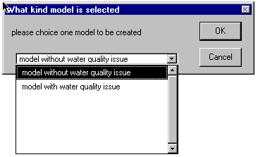
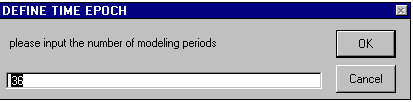
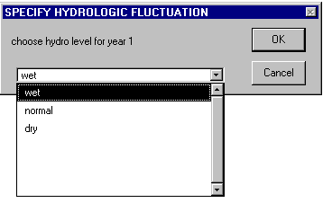
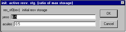
type. Figure 7 gives a demonstration for the interactions between the system
and users during the model constructing process, which include specifying
the initial modeling conditions, setting policy targets, selecting management
objectives and specifying objective weights etc. The system gives step-by-step
"what to do" message to users, and users just need to follow
the steps, and answer the questions, or make the choices. For some cases,
the system provides default values or conditions, and the user either take
or modify them.
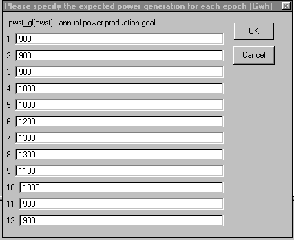
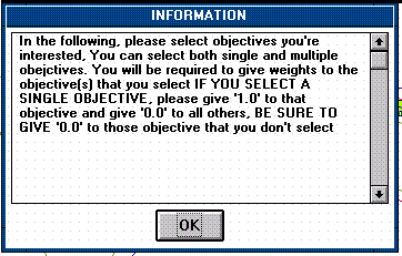
Figure 7 (1) - (7) Interactions
between the system and a user during model constructing process
7. Call a model
solver. When the model is ready, GAMS is called to run in a window within
Arcview, and the results from GAMS are read into Arcview data base.
8. View Results
click the "result view" button, and then follow the message boxes
to make some choices and see the results that are of interest. The results
are displayed as charts, tables, and message boxes. Figure 11 shows some
examples for the result view.
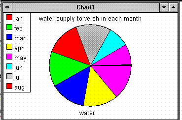 Figure 8 (1) - (3) Examples
for Result view
Figure 8 (1) - (3) Examples
for Result view
Summary
In this paper
we give a prototype GIS-based decision support system for river basin management,
and we use this prototype system to show how the spatial decision support
system (SDSS), which is a conjunctive application of GIS and DSS technologies,
can improve water resources management in a river basin. An object-oriented
approach is used to integrate a river basin visual representation and logical
representation into an operational framework, in which management analysis
can be made based on the river basin spatial dimension, physical laws embedded
in the river basin system, and management policies and decision preference.
The prototype
system provides several GIS-based functions, among which the network deriving
function and model generating function developed in this prototype allows
some work in river basin management to be done by computers automatically,
rather than by hand in the traditional way. Of course the most significant
thing is that the models generated in the prototype are tightly connected
to the real world spatial entities and their attribute data, so that the
system allows users to do water management analysis in a more efficient
and convenient way. The further development of these functions should be
promising for water resources planning and management.
This prototype
system is still under development. More work is needed to complete the
current prototype. For example, the model generation function can only
generate optimization models, and this function is to be updated so that
it can generate appropriate hydrologic simulation models (Yeh, 1996) water
quality simulation models, and economic models for river basin management.
References
Bennett, D. A., Armstrong, M. P., and
Weirich, F. (1996), "An object-oriented model base management
system for environmental simulation",
In GIS and Environmental Modeling: Progress and Research
Issues, edited by M. F. Goodchild
et al., GIS World Book, Fort Collins, 1996, 439-443.
Brooke, A., Kendrick, D., and Meeraus,
A.(1988). GAMS: a User's Guide, Scientific Press, san Fransisco.
Burgin, J., (1995), Automating the allocation
of water supplies in texas using an expert system to control
the interaction of a geographic information
system and LP solution algorithm, Ph.D. diss. , the University of Texas
at Austin.
Csillag, F (1996), "Variation on
hierarchies: toward linking and integrating structures", In GIS
and
Environmental Modeling: Progress and
Research Issues, edited by M. F. Goodchild et al., GIS World
Book, Fort Collins, 1996, 433-437.
Cowan, D. D., Grove, T. R. Mayfield, C.
I. et al. (1996), "An integrative information framework for
environmental management and research",
In GIS and Environmental Modeling: Progress and Research
Issues, edited by M. F. Goodchild
et al., GIS World Book, Fort Collins, 1996, 423-427.
Crosbie, P. (1996), "Object-oriented
design of GIS: a new approach to environmental modeling", In GIS
and Environmental Modeling: Progress
and Research Issues, edited by M. F. Goodchild et al., GIS
World Book, Fort Collins, 1996, 383-386.
Densham, P. J., and Goodchild, M. F. (1989),
"Spatial decision support systems: a research agency."
GIS/LIS'89 Proc. Vol2, American Congress
on Surveying and Mapping, Bethesda, Md.
Djokic, D., and Maidment, D. R. (1993),
"Creating an expert geographical information system: the
ArcInfo - Nexpert object interface",
In ASCE Monograph on Integration Issues in Expert Systems
Technology. New York: ASCE.
Esri (Environmental System Research Institute,
Inc., Redlands, Carlifornia, USA), Arcview 2.1 (3.0)
User's Manual, 1995 (1996).
Fedra, K, "Distributed models and
embedded GIS: integration strategies and case studies", In GIS
and
Environmental Modeling: Progress and
Research Issues, edited by M. F. Goodchild et al., GIS World
Book, Fort Collins, 1996, 414-417.
Fedra, K. and Jamieson, D. G., (1996),
"An object-oriented approach to model integration: a river basin
information system example", HydroGIS'96,
IAHS publ. no 235, 1996, 669-676.
Goodchild, M. F. (1993), "Data models
and data quality: problems and prospects", In Environmental
Modeling with GIS, edited by M.
F. Goodchild, B.O. Parks, and L. T. Steyaert, 8-15. New York: Oxford
University Press.
Lam, D. C., and Swayne, D. A., (1991),
"Integrated database, spreadsheet, graphics, GIS, statistics,
simulation models, and expert systems:
experience with the RAISON system on microcomputers" In
NATO, ASI Series, Vol. 26, edited by D.
P. Loucks and J. R. de Costa, 429-59, Germany.
Leipnik, M. R., Kemp, K. K. and Loaiciga
H. A. (1992), "Implementation of GIS for water resources
planning and management", J. Wat.
Resour. plng. Mgmt. : 119 (2), 184-205.
Loucks, D. P., French, P. N., and Taylor,
M. R., (1996), "Development and use of map-based simulation
shells for creating shared-vision models",
HydroGIS'96, IAHS publ. no 235, 1996, 695-702.
Loucks, D. P. , and da Costa, J. R. (1991).
Decision support systems water resources planning, NATO
ASI Series, Springer-Verlag, Berlin, Germany.
Mckinney, D. C., and Cai, X. "Multiobjective
optimization model for water allocation in the Aral Sea
Basin", the 2nd American Institute
of Hydrology (AIH) and Tashkent Institute of Engineers for
Irrigation (IHE) conjunct conf. on the
Aral Sea basin water resources problems, Tashkent, Uzbekistan,
July, 1996.
Mckinney, D.C., D. R. Maidment, and M.Tanriverdi,"Expert
geographic information sytem for Texas water
planning", J. of Wat. Resour.
Plng. And Mgmt.,119 (2): 170-183.
Nyerges, T. L. (1993), "Understanding
the scope of GIS: its relationship to environmental modeling", In
Environmental Modeling with GIS,
edited by M. F. Goodchild, B.O. Parks, and L. T. Steyaert, 75-84.
New York: Oxford University Press.
Pundt, H. , Hitchcock, A., Bluhm, M.,
and Streit, U. A., (1996), "A GIS-supported freshwater information
system including a pen-computer component
for field data recording", HydroGIS'96, IAHS publ. no.
235, 1996, 703-711.
Raper, J., and Livingstone, D. (1996),
"High-level coupling of GIS and environmental process modeling",
In GIS and Environmental Modeling:
Progress and Research Issues, edited by M. F. Goodchild et al.,
GIS World Book, Fort Collins, 1996, 387-390.
Reitsma, R. (1996), "Bootstrapping
river basin models with object orientation and GIS topology", In
GIS
and Environmental Modeling: Progress
and Research Issues, edited by M. F. Goodchild et al., GIS
World Book, Fort Collins, 1996, 457-461.
Walsh, M. R. (1992), "Toward spatial
decision support systems in water resources", J. of Wat. Resour.
Plng. and Mgmt. 109 (2): 158-169.
Yeh, Zichung (1996), "Object-oriented
hydrologic modeling ", Ph.D. diss., the University of Texas at Austin.
Authors:
Daene C. McKinney, Associate Professor
Dept. of Civil Engineering, the University of Texas at Austin, Austin,
Tx 78712; telephone: (512) 471-1807, email address: daene_mckinney@mail.utexas.edu.
Ximing Cai, Graduate Research Assistant,
Dept. of Civil Engineering, the University of Texas at Austin,
Austin, Tx 78712; telphone: (512) 471-0073,
email address: xcai@crwr.utexas.edu.
David R. Maidment, Professor, Dept.
of Civil Engineering, the University of Texas at Austin, Austin, Tx 78712;
telephone: (512) 471-0065, email address: maidment@crwr.utexas.edu.