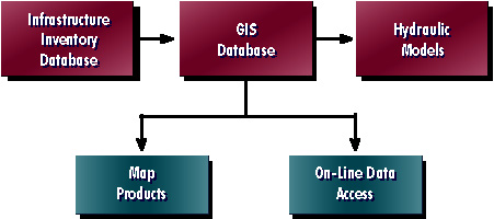
Primary objectives of the integration effort include utilization of the BC-OES' existing Oracle-based infrastructure management system database as a centralized database, development of an ArcInfo-based GIS database, Arcview-based query, display, and map generation tools, and development of Arcview-based applications to automatically prepare water and wastewater hydraulic models. The paper describes the methodology applied to integrate these three separate information systems with a focus on the preparation of hydraulic modeling applications and databases.
The presentation should prove useful to any water/wastewater utility planning to integrate GIS with hydraulic and water quality modeling and with master planning efforts.
Additionally, OES realized that many functions that require paper maps must be converted to direct data access using GIS software. Therefore the GIS viewing software must be easy to use and customize.
To mitigate organizational impacts, OES has made the decision not to update its master infrastructure database directly from the GIS environment. As new features are added to, or existing features edited in, the GIS maps, changes will be made to the master infrastructure inventory database in the traditional manner using the CASS WORKS software interface independently of the changes to the GIS database. Procedures will be implemented to notify those staff responsible for maintaining CASS WORKS of any changes. These procedures will need to be rigidly followed so that changes to the infrastructure inventory database and GIS are properly synchronized. These procedures will require close coordination between the operating and engineering divisions as they will have co-responsibility for the maintenance of the master infrastructure database and GIS. After the new information systems have been completely installed and tested, and the current OES LAN upgraded, OES may decide to update the master CASS WORKS database directly from the GIS.
To mitigate data access problems on the current OES LAN, a copy of select tables will be downloaded from the master infrastructure inventory database located on a file server in the OES operations division to the GIS file server located in the OES engineering division. The copy of the infrastructure database will be stored in an INFO format for rapid data retrieval in ArcInfo and Arcview as Oracle will not be installed on the GIS file server.
Data not accounted for in the master infrastructure inventory database, yet required for mapping and modeling, are stored in "supplemental tables" in an INFO format. These "supplemental tables" reside outside of the realm of CASS WORKS and are updated directly from the GIS. Automated applications using Oracle SQL and ArcInfo AML are being developed to maintain these data and to verify referential integrity between the CASS WORKS tables and the supplemental tables.
When OES engineering division updates its hydraulic models, modeling information are downloaded from the following locations:
Applications developed using Arcview/Avenue automate this procedure and ensure proper synchronization between the attributes and the graphics during model data preparation, warning OES staff of any inconsistencies noted during the data preparation process. Both modeling software applications, H2ONET for water and HydroWorks for wastewater, contain powerful data display, query, and specialized analysis tools, therefore providing all necessary functionality for review and analysis of modeling results and eliminating the need to upload model result data back to the master infrastructure inventory or GIS databases.
With these challenges in mind, the primary goals of the database design effort were:
Through numerous meetings and workshops, OES identified the GIS database design to facilitate the above listed goals. Of primary importance were the methodology used to classify water distribution and wastewater collection system facilities, topological configuration, and "granularity" of the GIS database [1].
CLASSIFICATION OF INFRASTRUCTURE FACILITIES
One primary objective of the GIS implementation and system integration was to link to existing data in the master inventory database whenever those data were available. With this in mind, a decision was made to implement in the GIS database the same classification and representation system of the master inventory database. OES had been using the CASS WORKS software prior to the beginning of the GIS implementation effort to store information on the OES wastewater collection system, yet very little information on the water distribution system was present in the master inventory database at the beginning of the GIS implementation. For that reason, more flexibility was afforded to the design of the water portion of the GIS database, as the master inventory database structure could be modified to match that of the GIS without impacting currently stored data.
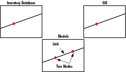
To illustrate the concept of facility classification, one can examine those instances where gravity sewers flow into lift stations. Where gravity sewers flow into lift stations, the OES operations division has structured the master CASS WORKS database so that the intersection point of a gravity sewer and lift station would be coded as both a "lift station" and as a "manhole", therefore allowing every gravity sewer in the master inventory database to be bounded by two manholes. To minimize impact to existing data in the CASS WORKS database, the GIS was structured in a similar fashion. In the GIS, the node at the end of each gravity sewer arc would be classified as both a lift station and a manhole. The node in the GIS database would therefore link two records in two different tables in the master inventory database. To facilitate recreation of the OES paper maps, which only show a lift station at such locations, only a cartographic lift station symbol will be placed at that node location.
TOPOLOGICAL CONFIGURATION AND GRANULARITY
To facilitate modeling activities, water and wastewater facilities in the GIS database must be topologically connected, that is to say that pipes must meet and must begin and end at one single coordinate where an intersection exists in the system. In the case of the OES system, pipes will also be broken at the following hydraulically significant locations:
This topological configuration matches that implemented by the CASS WORKS inventory database.
A decision was made to create a seamless database where pipes were not artificially broken at map sheet edges. This eliminated the need to develop automated procedures to "dissolve", or unbreak, pipes at these artificial nodes when downloading data to the hydraulic model databases. Additionally, pipes will not be broken at service connections, as they are not considered hydraulically significant and doing so would only increase the size of the GIS database.
Several challenges arise when moving data between a GIS, an infrastructure inventory database, and hydraulic models. Most significant is the differing representations implemented by the GIS and hydraulic models to represent the same facility types. In the GIS, hydraulically significant facilities such as valves are usually represented as points, whereas a linear representation of the same facility is required in the models. Also significant is the selection of network facilities to be modeled. To facilitate master planning activities, OES' hydraulic models require only portions of the entire water and wastewater facilities represented in the GIS and master inventory databases.
DATA TRANSFORMATION
A conflict arises between the GIS and infrastructure inventory databases, which both represent some water/wastewater system facilities in one fashion, and the hydraulic modeling software, which represent and model the same facilities in an entirely different fashion. A flow control valve in the water system, for instance, is represented as a point (single X, Y coordinate with a unique identifier) in the GIS to facilitate cartographic replication of the paper maps, whereas a flow control valve is represented as a linear feature with discrete "upstream" and "downstream" nodes in the hydraulic model.
Several methods exist for creating the linear representation of hydraulically significant facilities from point-based representations in the GIS. Two methods were identified to facilitate this transformation. The first method, which can be referred to as "claiming an existing element" [2], involves inheriting a pipe adjacent to the node and re-classifying the entire pipe as the node entity. This method was discounted as the adjacent pipe may be of significant length and the pipe's length would be lost if the node information was transferred to that linear element in the model, thereby adversely affecting the model database. The second method, which can be referred to as "element fragmentation" [2], involves breaking an adjacent pipe to create a new linear element that would contain the attributes of the hydraulically significant node, as illustrated in Figure 3 below:
The linear element representing the hydraulically significant node is identified in the model using the same identifier as that in the GIS database. The new model node used to break the adjacent pipe is given a new, unique identifier generated as a function of the identifier of the node for which a linear representation is being created:
An automated procedure was developed using Arcview Avenue to transform the point-based representation of the facility in the GIS to the linear representation of the facility in the hydraulic model using the element fragmentation methodology as illustrated in Figures 3 and 4. The length of the original pipe element is preserved in the model, and length is not stored for the linear representation of the node feature, as none is required in the model. The locations (X,Y coordinate) defining each break point on the adjacent pipes are user-defined by adding points to an Arcview theme. This allows OES modelers to control the visual length of the new linear element as desired. The shapefile containing these "model nodes" is used by the data downloading application to define the element fragmentation points. Should a model node not be added to the Arcview theme by OES staff, the program warns the user that model inputs cannot be properly generated until the required information is added to the theme. Element fragmentation occurs for pressure and flow control valves, water pump stations, and sewer lift stations.
MODEL SIZE REDUCTION
To support master planning activities, OES realized that not all facilities are required in the hydraulic models. Flags were added to the GIS database to facilitate automated selection of network facilities for inclusion in the modeling databases. Facilities are being flagged for inclusion in the model during the data conversion task. The following facilities are to be included in the hydraulic models:
Using this methodology, OES staff do not have the opportunity to build custom modeling databases using the automated data translation program. This program will always select elements for inclusion in the model database based on the database flags set during data conversion.
APPLICATION METHODOLOGY
Upon initiation of the download process, the OES technician must indicate for which of the three retail service districts the model is being prepared, which utility layer is being modeled (potable water, raw water, or sanitary sewer), for which planning period the model is being prepared for (existing system only, 5-year planning period, 10-year planning period, etc.), and the names and storage locations of the model input files. Information is extracted from pertinent database tables in the master CASS WORKS database and graphical information including node locations, pipe lengths, and pipe shape (OES desires a curvilinear representation of piping in the modeling software rather than a generalized "node-to-node" representation) are extracted from the ArcInfo GIS coverages and Arcview shapefiles. These data are then re-formatted as required by the H2ONET and HydroWorks modeling software packages. At that point, OES planners receive the data, import the data into the respective modeling software packages (using standard import functionality provided by each), run and evaluate the models.
Several carefully planned steps must be taken to successfully implement a water/wastewater GIS and to integrate that GIS with other information systems. Through a properly designed database, data can be efficiently shared by separate information systems and applications. By using the facility classification scheme and topological configuration defined by the master infrastructure inventory database in the GIS database, GIS maps can be linked to the master database with little or no data translation. Custom applications developed in Arcview allow OES to migrate data between the GIS and model databases even though there are significant differences in data representation between these two information systems. Additionally, custom software applications facilitate data translation with a minimal amount of effort required on the part of OES staff. The GIS implementation within the Broward County Office of Environmental Services is ongoing, but with carefully developed software applications, proper training and documentation, understanding of GIS database design and project goals, OES staff will be able to realize the benefits of integrating three traditionally separate information systems.
[1] DiSera, D., Lerner, N. 1997. "Utility Map Automation: What Every Manager Should Know." Proceedings AWWA Computer Conference, Austin, Texas, April, 1997.
[2] Graybill, G. 1997. "Strategies for Interoperation between a Network Modeling System and a GIS." Proceedings AM/FM International Annual Conference, Nashville, Tennessee, March, 1997.
Mr. Daniel H. Feinberg
GIS Specialist
Montgomery Watson Americas, Inc.
560 Herndon Parkway, Suite 300
Herndon, Virginia, 20170-5240, U.S.A.
Phone (703)478-3400
FAX (703)478-3375
E-mail dan.feinberg@us.mw.com
Mr. Steven W. Uhrick, P.E.
Chief, Technical Support Section
Broward County Office of Environmental Services
2555 West Copans Road
Pompano Beach, Florida, 33069, U.S.A.
Phone (954)831-0931
FAX (954)831-0925
E-mail suhrick@co.broward.fl.us