Robert Lussier and Jia Hao Wu
Development of a Data Exchange Protocol between EMME/2 and ArcInfo
Abstract
Sharing spatial information between a transportation planning software (like
EMME/2) and a GIS (like ArcInfo) is a complicated task, both in terms of data
structure and informational needs.
INRO Consultants established guidelines to standardize the
creation of a transportation planning coverage and developed a set of
tools to transfer information between EMME/2 and ArcInfo.
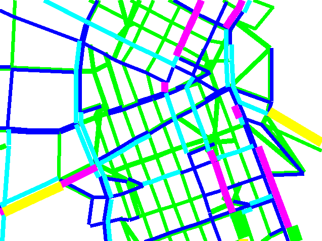
In this paper, we identify the motivation for the development of
a data exchange procedure between ArcInfo and EMME/2. Then we identify
the corresponding data items in ArcInfo and EMME/2, discuss the
communication process for exchanging data and computed results
between the two systems, and develop a user-friendly interface to
realize the data exchange. As a concrete example, we present a
prototype of the system for the EMME/2 road and transit network, which
can be used to display the attributes and results obtained in EMME/2.
Future developments and possible applications of this system are
discussed as well.
A) Motivation
GIS software packages are used mainly as a tool for managing spatial
information and performing associated computations. They have good database
management features and boast effective manipulation and representation of
spatial data.
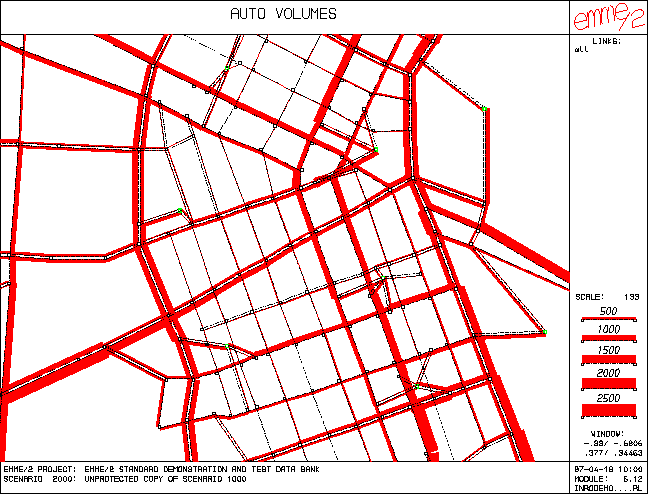
Unfortunately, for the purposes of transportation planning, they offer a
limited set of tools. The transportation planner deals with an aggregate
representation of networks (current and future) and wants to compare different
scenarios in order to make a recommendation. This information cannot be
obtained from a typical GIS. To assist the planner in more complex and specific
tasks other software packages, like EMME/2, offer a working environment that
incorporates some spatial data manipulation features and, above all, provide strong network assignment and demand modeling
capabilities.
Since much effort is usually invested in the creation of databases
(be it at the city, county, or state levels) to manage spatial information
within a GIS, it would be beneficial to be able to share data and analysis
results in order to expand the database.
It is costly to maintain different databases for different applications in
different departments. Therefore, the goal is to integrate these databases into
a common multi-purpose database. Our efforts serve as a contribution towards
the compatibility of spatial information, as requested by the GIS community.
In this paper we consider ArcInfo as the GIS software package, and EMME/2 as
the transportation planning software package.
B) Objectives
The objectives of this project are:
- To establish the relationship between features and attributes in both
software packages;
- To establish guidelines to create a standard information structure that
corresponds to a transportation planning infrastructure in ArcInfo;
- To implement a prototype application following these guidelines to
ease the data transfer process between the two software packages.
C) Data models of ArcInfo and EMME/2
C1) EMME/2 road and transit network data model
The EMME/2 data model is divided into three main categories:
- Network: it describes the transportation infrastructure, and is defined
by the following elements:
- modes: they are grouped in four types:
- auto mode
- transit modes (ex.: bus, train, tramway)
- auxiliary transit modes (ex.: pedestrian)
- auxiliary auto modes (ex.: trucks, high occupancy vehicles)
- base network: both road and transit networks are highly integrated in
what is called the base network; it consists of nodes and links,
which are divided as follows:
- a regular node may correspond to an intersection, a transit stop, etc.
- a centroid is a node associated with a zone: all trips from and to the zone originate and end at that node
- a link is a directional connection between two nodes, using one or more modes
- a connector link is a link which connects a centroid to a regular node
- turns: they represent possible turning movements at an intersection;
some of them may be penalized or prohibited;
- transit vehicles: they correspond to vehicles or combinations of
vehicles that may be used by a transit line (e.g.: regular or
articulated buses, trains consisting of several cars, etc.);
- transit lines: they correspond to regular transit services (fixed
frequencies and travel times) on a fixed itinerary; each itinerary
is defined as a sequence of transit segments, each of them
corresponding to a link in the base network.
Each of these elements may have attributes, which are subdivided into
three types:
- standard attributes are a part of the basic network data. These
attributes have predefined names, most of them have a special
meaning (e.g.: link length), and include three user data items.
- extra attributes are other user-defined attributes. They are created
by the user, who gives them a name, a description and a
default value.
- assignment results, when available, are stored with some network
elements (links, turns, and transit line segments).
This network data set forms a scenario, and an EMME/2 data bank may
contain several scenarios. For example, one scenario may correspond to
the base year, while others may represent different network variants
envisaged for future years.
EMME/2 stores information in a "vertically" structured data format (each
element attribute, such as link length, is stored in a vector). Compared to
a "horizontal" structure, where a row in a table contains all the
attributes of an element, a "vertical" one makes efficient use of the
available computer memory space and also drastically reduces the number of
disk accesses required to quickly and selectively access the EMME/2
data bank.
- Matrices: they are the standard means by which EMME/2 stores zone-related data:
- Matrices can be used to store input data (demand, socio-economic
data, etc.) as well as results (travel time, travel distance, etc.);
- There are four types of matrices: full (O-D), origin, destination,
and scalar;
- A zone is identified by a centroid number; zones can be grouped into
zone groups which are defined as sets within ensembles.
- Functions: they are data structures which contain algebraic expressions
describing functional relationships. They are divided into six classes:
- an auto volume-delay function gives the travel time (in minutes) on
a link of the auto network, as a function of link attributes;
- a turn penalty function gives the time for a turn (in minutes), as a
function of turn attributes;
- a transit time function gives the travel time (in minutes) on
a transit line segment, as a function of link, vehicle, line, and
segment attributes;
- an auto demand function gives the auto demand (in persons), as a
function of matrices and zone numbers;
- a transit demand function gives the transit demand (in persons/hour),
as a function of matrices and zone numbers;
- a user-defined function is not linked to the data in the data bank.
It permits the user to enter, manipulate and display functions of
his choice by using general keywords.
C2) ArcInfo network data model
ArcInfo supports many data models (coverage, grid, triangulated irregular
network, CAD, etc.) to represent geographic information. A coverage is for
vector data, and supports georelational models, that is, it contains both
the spatial and attribute data for geographic features. The feature classes,
used in the coverage to store geographic features, are:
- points for storing punctual features;
- arc, node and route-system for storing linear features;
- polygon and region for storing areal features.
ArcInfo stores coordinates only for points, arcs, and nodes, and uses
topological relationships for defining networks and polygons. Here are the
three topological concepts used to define features:
- The arc-node topology defines the connectivity of arcs; arcs are composed of
two nodes and up to 500 vertices, and are connected at nodes; a set of
connected arcs can define a network (streets and intersections);
- A polygon is defined as an ordered series of connected arcs, but the first
and the last arcs must connect (area definition topology); for each arc,
the left and right polygons are identified (left-right topology).
Networks and polygons form the framework for defining the two other feature
classes:
- Route-systems are defined as an ordered series of arcs, however the
first and last arcs need not connect. They are composed of:
- Routes, which are linear features composed of one or more sections;
- Sections, which may be an arc or portion of an arc used to define a
route; a section is the most basic component of a route-system.
In the dynamic segmentation model, route-systems are used to model linear
features using route-measures and events, and to associate multiple sets of
attributes to any portion of a linear feature.
- Regions are defined as a set of polygons.
To represent transportation networks, ArcInfo uses the previous feature
classes as the basis of the NETWORK data model. The model consists of:
- network links representing the interconnected linear entities that
are the conduits for transportation, they are modeled as
ArcInfo arcs; links are bidirectional (by the means of from-to
and to-from link impedances: if the impedance is positive, then
flow can travel in that direction, if it is negative,
the flow is forbidden); the network link attributes are stored
in the arc attribute table (AAT);
- network nodes representing the endpoints of network links; they are
modeled as ArcInfo nodes; the node attributes are stored in
the node attribute table (NAT);
- stops, which are nodes representing locations visited in a path
(shortest path algorithm) or tour (traveling salesman problem);
stops and stop attributes are maintained in INFO files,
referred to as stop files;
- centers, which are nodes representing resource supply or some type
of attraction; centers and center attributes are maintained in
INFO files, referred to as center files;
- turns representing transitions from one network link to another
network link at nodes; turns are listed and maintained
separately in a coverage INFO file called a turntable (TRN).
Since the transit system uses some of the arcs of the transportation network
and is defined by different data attributes, it is best represented by
dynamic segmentation (route-system and events). It is composed of the
following elements:
- a transit line is represented as a route; the transit line attributes are
maintained in the route attribute table (RAT);
- a transit line segment is represented as a section; the segment attributes are
maintained in the section table (SEC).
C3) Relationship between data elements and features contained in both models
The following table contains general object descriptions found in a
transportation planning infrastructure, and the corresponding element in
both software packages:
Objects | ArcInfo items | EMME/2 items
|
street | route | -
|
street section | section | -
|
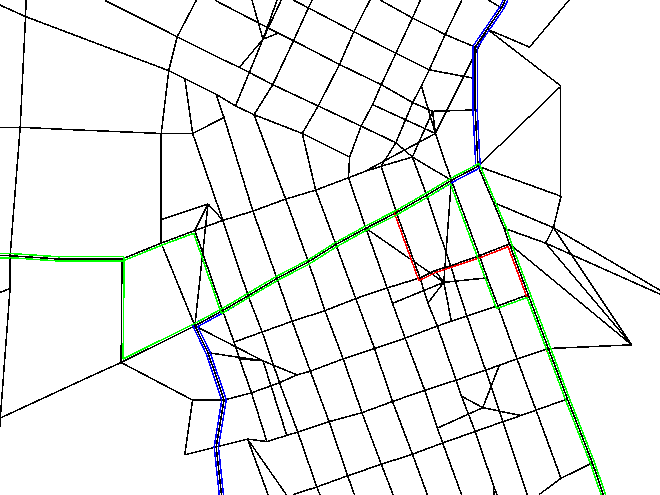
directed street section | arc | link
|
intersection | node | node
|
traffic light | node | node
|
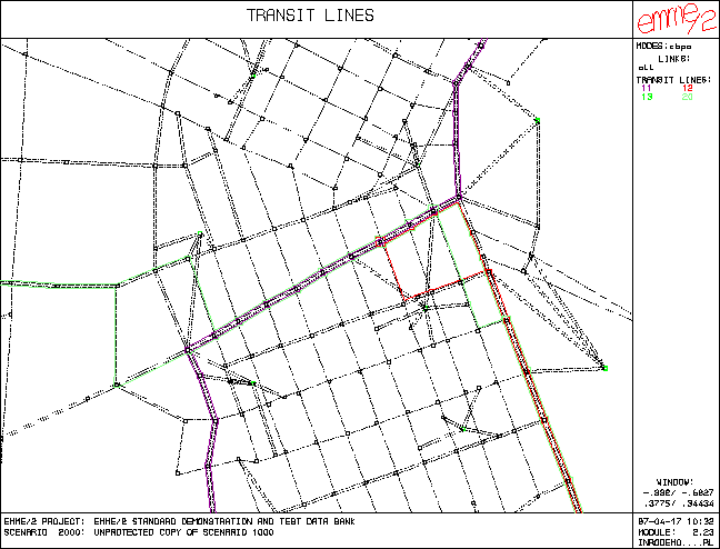
transit line | route | line
|
transit section | section (within a route) | segment (within a line)
|
transit stops | point event, node | node
|
region | region | zone, group, ensemble
|
TAZ (traffic analysis zone) | polygon | zone
|
Origin and Destination | node, center | centroid
|
O-D matrix | - | matrix
|
supply center | node | centroid
|
demand center | node | centroid
|
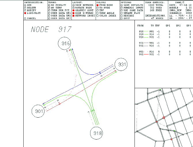
turns | turn (arc-node-arc) | turn (at_node-from_node-to_node)
|
arc-to-arc barrier | arc selection set | turn penalties
|
drawing | polyline, patterns | annotation, demarcations
|
text | annotation | annotation
|
C4) Differences and "inconsistencies" between the two data models
| ArcInfo | | EMME/2
|
- | arcs can be bidirectional (with directional attributes) | - | links are unidirectional (represent flow of traffic)
|
- | each arc can be composed of up to 500 vertices, including from-node and to-node | - | each link is composed of an i-node (from-node) and a j-node (to-node)
|
- | a node is created by the CLEAN command when two arcs crossover (polygon topology) | - | links can pass one over another
|
- | bus stops can be stored as point events which are not necessarily represented by nodes at the arc-node level | - | bus stops must be represented by a node
|
- | all feature attributes are stored in a relational-like data base ("horizontal" structure) that is managed by the INFO information manager (or other external relational data base managers) | - | element attributes are stored in a "vertical" structure
|
- | tables are mostly user-defined depending of the user applications and data needs | - | many of the attributes are already defined (standard attributes)
|
D) The communication process
Although it seems natural to consider a direct communication process between
an ArcInfo workspace (Master GIS) and an EMME/2 data bank, there are several
difficulties involved. For example, given an ArcInfo workspace where there are a
road network and a transit network, we still have to define traffic zones and
decide on a certain aggregation of the network representation for some specific
applications. This can only be carried out by the transportation planners and
not by an automatic process. In order to establish an automatic process that can
exchange information between the two software packages, we decided to establish an
EMME/2 coverage in ArcInfo with a "one-to-one" relationship with the EMME/2
network elements. The communication paths are shown in Figure 1.
Note that there is no specific sequence in this figure.

Figure 1 - General components involved in the joint utilization of ArcInfo and EMME/2
The ArcInfo workspace is considered to be a database created independently
by ArcInfo users from their organizational point of view (policy, MIS
standards, etc.). Therefore, one may expect a variety of data definitions and
data contents stored in this database. The representation of real-world
entities may vary in detail.
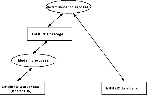
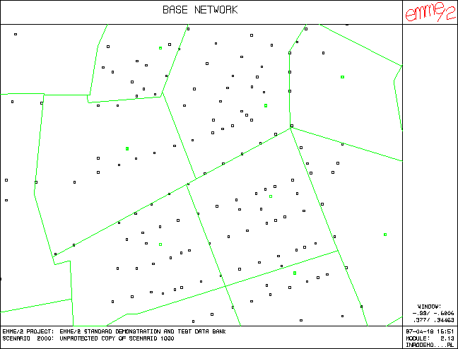
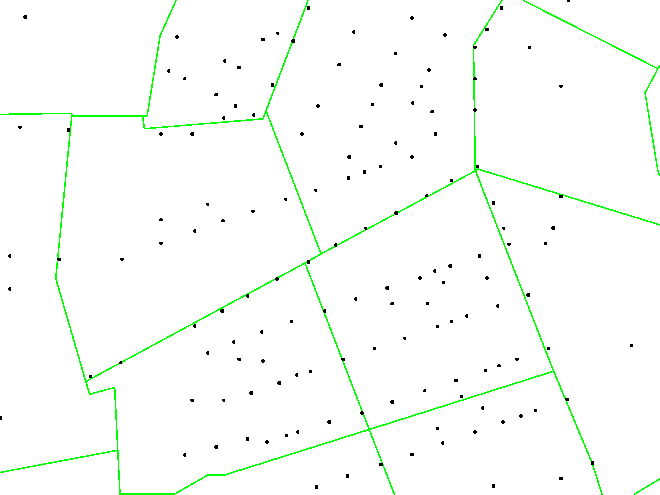
The EMME/2 data bank is an aggregate representation of the transportation
infrastructure, the economic activities and the socio-economic characteristics
of the urban area studied.
The EMME/2 coverage follows the EMME/2 network representation. This implies:
- the base network is an aggregate representation of reality and must
respect the one-to-one relationship of the transit network (one stop equals
one node); the road infrastructure and attributes are stored at the arc
level;
- for the transit network, the infrastructure is represented by a
route-system where one segment corresponds to one arc; the itinerary will
be kept within a transit line on the basis of the section measures;
- for the zones, all data will be stored in a different coverage (because we
need to use the CLEAN command to create the polygon topology, and that
would create unnecessary nodes in the base network).
The goal of the communication process is to integrate the two databases in a
standard way. There are four cases to consider:
- Case one: There is an EMME/2 data bank but no ArcInfo workspace. One must
extract information from the EMME/2 bank and then convert it into an
ArcInfo coverage.
- Case two: There is an ArcInfo workspace but no EMME/2 data bank. The goal
is then to export the ArcInfo coverage and convert it into an EMME/2
format.
- Case three: There is neither an ArcInfo workspace nor an EMME/2 data bank.
In this case, the user will decide which one to establish first
depending on the objectives of the applications and timing
considerations. In that case, one sees the importance of submitting
guidelines to build one and the other.
- Case four: Both the EMME/2 data bank and the ArcInfo workspace exist but
have been built separately. This is the most complex case. The
integration of these two networks can be done by using techniques such
as rubber sheeting (stretching the coordinates of the elements of
one network to match the elements of the other), conflation (aligning
two coverages and transferring the attributes from one to the other), etc.
The modeling process represents the transformation of the user network in the
master GIS into the EMME/2 coverage. This can be complex or simple depending
on the design of the database. In order to create the EMME/2 coverage from an
existing master GIS, the planner has to take a road network coverage and
convert it into an aggregate representation by removing unnecessary details,
merging some arcs together and reevaluating attributes. Also, if the
transportation network includes a transit network, the planner has to take the
route-system representing transit lines and split underlying arcs at bus stops
to create a node. This process must include a procedure to keep the
correspondence between the user network and the base network of the EMME/2
coverage. The modeling process is specific to the organization where it is
implemented.
E) Data structure of the EMME/2 coverage

Figure 2 - Entity-Relationship Diagram
The EMME2.AAT table stores information related to the arcs of the EMME/2
coverage, and its definition follows the NETWORK data model of
ArcInfo. This implies that, since one arc may be travelled in two directions,
each attribute of the arc is represented by a from-to attribute and a
to-from attribute. The first six fields of this table are standard and
contain internal information. They are created by ArcInfo when building the
arc-node topology. The EMME2-ID field is used to store a unique arc
identifier number in order to maintain the correspondence between an arc in
ArcInfo and a link in EMME/2. If the EMME/2 coverage is derived from an
existing user coverage in the master GIS, then this number is already
present and can be directly exported to an extra attribute in the EMME/2
data bank. However, if the EMME/2 coverage is derived from an EMME/2 network,
this identifier must be evaluated in EMME/2. Since a two-way street,
represented by two links in EMME/2, is represented by only one arc in
ArcInfo, one needs to compute the identifier based on the internal link
index of the EMME/2 data bank, and keep the result in an extra attribute (by
default @arcid). The EMME2-ID is computed as follows:
- the link table is scanned in ascending internal index number, and all
links are assigned an index number;
- for all two-way links, the first link encountered will be assigned
a positive identification value while the reverse link (the link in
opposite direction) will be assigned zero minus this same value.
This is easily done with an EMME/2 macro. This distinction is required in
order to establish which information is related to the from-to direction and
which to the to-from direction. The table definition of EMME2.AAT can be
found in Appendix A.
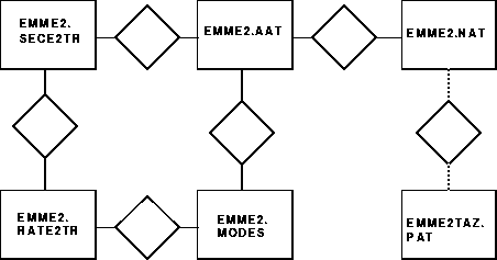
The EMME2.NAT table stores information related to nodes. The first two
fields of this table contain internal information, also created when building
the arc-node topology, and are maintained by ArcInfo. The EMME2-ID field is
used to store the EMME/2 node number. Again, if the EMME/2 coverage is derived
from an existing user coverage in the master GIS, then this number is already
present, and can be directly used as the node identifier in EMME/2. However,
if the EMME/2 coverage is derived from an EMME/2 network, this identifier
should be computed using the relation between FNODE# and TNODE# fields of the
EMME2.AAT table, and the EMME2# field of the EMME2.NAT table. Since the INODE
and JNODE fields of the EMME2.AAT table contain the EMME/2 node number and
are related to the FNODE# and TNODE# respectively, the EMME2-ID is computed
as follows:
- the FNODE# and INODE information is extracted from the EMME2.AAT
table and stored in an INFO file;
- the TNODE# and JNODE information is extracted from the EMME2.AAT
table and appended to the same INFO file;
- this INFO file is joined to the EMME2.NAT table based on the internal
node number.
The user must also indicate, in a field called CENTROID, which of these
nodes are considered as centroids/centers (with a value of 1) and which as
regular nodes (value of 0). The table definition of EMME2.NAT can be found in
Appendix A.
The EMME2.MODES table is used as a lookup table for the transportation mode
definitions, and is maintained by the user. It may be used for query purposes
of mode on arcs (EMME2.AAT) or transit lines (EMME2.RATE2TR). It could be
directly obtained from the EMME/2 mode definitions. The table
definition of EMME2.MODES can be found in Appendix A.
The EMME2.RATE2TR table stores information about transit line definitions,
while the EMME2.SECE2TR table is used to store information about transit line
segments. The first field of RAT and the first seven fields of the SEC table
are maintained by ArcInfo and are created when a route-system is built.
Because we decided to keep a one-to-one relationship between a section and
an arc, we have the same relationship between a section (in ArcInfo) and a
segment (in EMME/2). The E2TR-ID field of the EMME2.SECE2TR table is used to
store a unique section identifier number which assures the correspondence
between a section in ArcInfo and a segment in EMME/2. If the EMME/2 coverage
is derived from an existing user coverage in the master GIS, then this number
is already present, and can be directly exported to an extra attribute in the
EMME/2 data bank. However, if the EMME/2 coverage is derived from an EMME/2
network, this identifier must be evaluated in EMME/2. One needs to compute the
identifier based on the internal segment index of the EMME/2 data bank and
keep the result in an extra attribute (by default @segid). The E2TR-ID is
computed as follows: for each transit line, the value of each segment within
the line is assigned to the internal segment number plus the value of a
variable; this variable contains the maximum segment value of the previous
transit line evaluated. We thus obtain a unique value for each segment within
all transit lines. This is easily done with an EMME/2 macro.
The ROUTE-ID field (of the EMME2.SECE2TR table) contains an integer value
representing the transit line number. It is equivalent to the E2TR-ID field
of the EMME2.RATE2TR table. In EMME/2, transit lines are identified by a six
character string (LINENAME field of EMME2.RATE2TR table) while in ArcInfo a
route is identified by an integer. When exporting to EMME/2, the ROUTE-ID can
be directly used as the transit line identifier in EMME/2. When exporting
from EMME/2 to ArcInfo, however, a unique numeric line identifier must be
computed from the internal line number. The table definitions
of EMME2.RATE2TR and EMME2.SECE2TR are in Appendix A.
The EMME2.TRN table stores information related to turns and is created by
the TURNTABLE command. The first seven fields of the TRN table contain
internal information and are maintained by ArcInfo. The TURN-ID field
contains a unique value for each turn, and is evaluated with the expression:
ARC1-ID * 100000 + ARC2-ID. It is used to facilitate the joining of attribute
tables if specific turn attributes are coming from the EMME/2 data bank.
The table definition of EMME2.TRN is in Appendix A.
The EMME2TAZ.PAT feature table stores information related to traffic analysis
zones. The first three fields of this table are standard and contain
internal information. They are created by ArcInfo when building the polygon
topology. The EMME2TAZ-ID field is used to store a unique zone identifier
number in order to keep the correspondence between a polygon in ArcInfo and
a zone in EMME/2. Since this zone number is also related to the centroid
number, you can relate information from the EMME2TAZ.PAT table and the
EMME2.NAT table. If the polygon data is coming from an EMME/2 annotation
file, the centroid number must be indicated at the beginning of the polygon
definition. Appendix A contains the table definition of EMME2TAZ.PAT.
Other attributes (assignment results, extra attributes, ...) can be
added as an additional column in the corresponding table. The name of the
column should be the same as the name found in EMME/2.
We have chosen to store the road network information in the AAT instead
of in a route-system since it is closest to the one-to-one relationship and
since many ArcInfo users are probably familiar with the NETWORK data model.
F) Implementation
As a test bench, we have implemented a prototype that extracts, converts
and inputs ASCII data from EMME/2 to ArcInfo (E/2->A/I) and vice versa
(A/I->E/2). For this implementation, we have considered the first three cases
mentioned in the communication process section. The fourth case is more
complex, and is not addressed by the prototype. EMARC, the name of the
prototype, is composed of:
- AML (Arc Macro Language) scripts and menus: they are used to
- establish the basis for the graphical user interface (GUI)
- create the EMME/2 coverage and add the feature attributes
- call external scripts and macros for data extraction (E/2->A/I) and conversion
- perform some GIS operations
- extract coverage data and convert it to EMME/2 format (A/I->E/2)
- EMME/2 macros: they are used for exporting and importing EMME/2 data
- AWK scripts: they are used to convert ASCII outputs from a software into a format readable by the other
The prototype is divided in two main parts: the EMME/2 to ArcInfo interface
and the ArcInfo to EMME/2 interface.
EMME/2 to ArcInfo interface
This option converts a specified EMME/2 scenario into an EMME/2 coverage in
ArcInfo. Four different types of information can be converted:
the base network and related attributes, the turns and related attributes, the
transit lines and related attributes, and the zones and related attributes.
The base network and related attributes
This sub-option allows the user to create the EMME/2 coverage and to input
spatial data (arcs and nodes). It uses AML, EMME/2 macros and AWK scripts to
punch spatial and standard attribute data from the EMME/2 data bank, convert
all punched data into an ASCII format readable by ArcInfo, create the EMME/2
coverage, input spatial information into that coverage with the GENERATE
command, and create the arc-node topology. Also, all standard attribute
information is entered into the AAT, the NAT, and mode table, and
additional fields are computed to keep the correspondence between the two
data bases. The user also has the possibility to add other
attributes (assignment results, extra attributes or other derived attributes)
to any feature tables by specifying the name of the attribute.

Figure 3 - Base network in EMME/2

Figure 4 - Base network in ArcInfo
The turns and related attributes
This sub-option allows the user to input turn definition and attribute data.
It uses AML, EMME/2 macros and AWK scripts to punch all turn data and standard
attribute data from the EMME/2 data bank, convert all punched data into an
ASCII format readable by ArcInfo, create the coverage TRN file using the
TURNTABLE command, and inputs attribute data into that file. The user also has
the possibility to add other attributes (assignment results, extra
attributes or other derived attributes) to the TRN table by specifying the
name of the attribute. The information contains in this table cannot be plotted
in ArcInfo.

Figure 5 - Turns in EMME/2
The transit network and related attributes
This sub-option allows the user to create a route-system representing
the transit network in the EMME/2 data bank, and input standard attribute data
for route sections. It uses AML, EMME/2 macros and AWK scripts to punch
transit line definitions and standard attribute data from the EMME/2 data
bank, and to convert all punched data into an ASCII format readable by ArcInfo.
For the creation of the route-system holding the transit lines, we have
investigated and implemented two methods:
- The first method is based on the PATH command of the NETWORK module.
It uses as input a stop file containing a node number for each stop,
and a value representing the order in which the nodes will be
visited.
- The second method is an iterative method which, for each transit line,
creates the route using the MAKEROUTE command of ARCEDIT. It appends
all the sections iteratively using the APPEND command of ARCEDIT,
until the end of the transit line.
Our experience shows that whenever the NETWORK module is available, the first method
should be used, because it is much faster than the iterative method.
Again, the user also has the possibility to add other attributes (assignment
results, extra attributes or other derived attributes) to the SEC table by
specifying the name of the attribute.

Figure 6 - Transit network in EMME/2

Figure 7 - Transit route-system in ArcInfo
The zones and related attributes
This sub-option allows the user to create the EMME/2 polygon coverage and to
input zone attribute data into the Polygon Attribute Table (PAT). It uses
AML and AWK scripts to convert EMME/2 annotation files into an ASCII format
readable by ArcInfo, creates the EMME/2 polygon coverage, inputs spatial
information into that coverage with the GENERATE command, and creates the
polygon topology. Finally, the polygon attributes are entered in the PAT.
While in the current implementation we do not transfer origin or destination
matrix data into the PAT, we consider this is an easy task.

Figure 8 - Zones in EMME/2

Figure 9 - Polygons in ArcInfo
The whole importing process takes about 120 seconds (on a SPARC 1000E) to
transfer a small network of 150 zones, 2975 links, 67 transit lines, and 4205
line segments.
ArcInfo to EMME/2 interface
This option converts a specified EMME/2 coverage of the ArcInfo data base into
a specified scenario of the EMME/2 data bank. It uses the EXPORT command of the
ARC module to export feature tables (AAT, NAT, PAT, TRN) in ASCII format.
The UNLOAD command of the TABLES module is also used to create ASCII files for
non-feature tables (MODES, etc.). Some AWK scripts are used to convert these
ASCII files into EMME/2 data files, which are then read into the EMME/2 data
bank using EMME/2 macros.
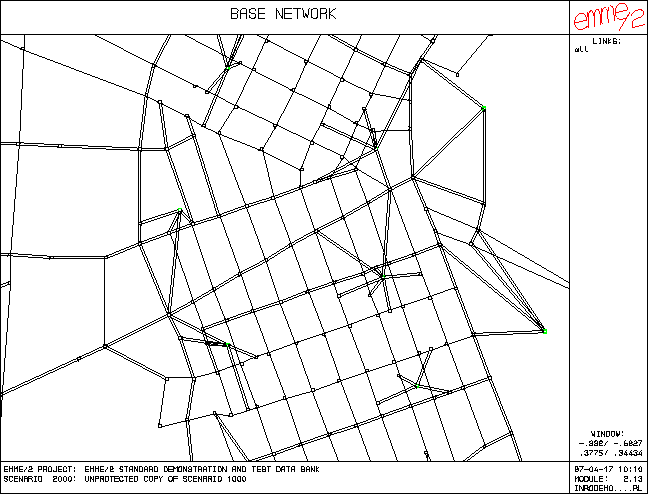
The whole exporting process takes about 100 seconds (on a SPARC 1000E) to
transfer the same small network (150 zones, 1607 arcs, 67 transit lines, and
4205 line segments).
Other option
Another option included in the prototype lets the user plot the base network of
the EMME/2 coverage in terms of its directional attributes. A specified
attribute is presented in each direction in terms of bar and color depending on
the attribute value.

Figure 10 - Attribute on base network in EMME/2

Figure 11 - Attribute on base network in ArcInfo
While the prototype described here uses ASCII files for the conversion
process, the guidelines and data structures that we have developped can
equally be used in the context of binary data exchange.
G) Conclusion
The one-to-one relationship constraint imposed on the EMME/2 coverage eases the
process of exchanging data between the EMME/2 data bank and the ArcInfo data
base. However, when both the EMME/2 and ArcInfo data bases were designed
independently, this constraint implies that the modeling process (see Figure 1)
may be very complex, depending on the design of the network coverage in the
master GIS. Therefore, there is a need to develop more tools to ease the task
of extracting sub-area network from a network contained in an ArcInfo master
GIS.
The data exchange process described here is static in nature and does not address
the dynamic aspect of the problem: if small modifications are made in one data bank,
the complete data set must be exported again. However, we see the current communication
process as a necessary starting point toward a dynamic conncection.
H) References
INRO Consultants Inc., EMME/2 User's Manual, Montreal, Quebec, CANADA, 1996.
Esri Limited, ArcDoc ver. 7.0.4, Redlands, CA, USA, 1995.
Appendix A
This appendix contains the INFO table definitions of the EMME/2 coverage.
Road Network data:
DATAFILE NAME: EMME2.AAT 03/12/1997
27 ITEMS: STARTING IN POSITION 1
COL ITEM NAME WDTH OPUT TYP N.DEC Description
1 FNODE# 4 5 B - Internal node number of the
from-node of the arc
5 TNODE# 4 5 B - Internal node number of the
to-node of the arc
9 LPOLY# 4 5 B -
13 RPOLY# 4 5 B -
17 LENGTH 4 12 F 3
21 EMME2# 4 5 B -
25 EMME2-ID 4 5 B - A unique arc identifier number which
assures the correspondence between an
arc in ArcInfo an a link in EMME/2
29 INODE 8 8 I - EMME/2 node number for the from-node
37 JNODE 8 8 I - EMME/2 node number for the to-node
45 LEN 4 12 F 3 EMME/2 link length
49 LENR 4 12 F 3 Same as above for the opposite direction
53 LANES 4 8 F 1 Number of lanes
57 LANESR 4 8 F 1 Same as above for the opposite direction
61 TYPE 6 6 I - EMME/2 link type
67 TYPER 6 6 I - Same as above for the opposite direction
73 VDF 6 6 I - EMME/2 volume delay function number
79 VDFR 6 6 I - Same as above for the opposite direction
85 UL1 4 8 F 2 EMME/2 user defined link data
89 UL1R 4 8 F 2 Same as above for the opposite direction
93 UL2 4 8 F 2 See UL1
97 UL2R 4 8 F 2 See UL1R
101 UL3 4 8 F 2 See UL1
105 UL3R 4 8 F 2 See UL1R
109 MODE 6 6 C - List of modes allowed on the link
115 MODER 6 6 C - Same as above for the opposite direction
121 SYMBOLS 4 8 F 2 Information used by the plotting routine of the prototype
125 SYMBOLSR 4 8 F 2 Same as above for the opposite direction
DATAFILE NAME: EMME2.NAT 03/12/1997
9 ITEMS: STARTING IN POSITION 1
COL ITEM NAME WDTH OPUT TYP N.DEC Description
1 ARC# 4 5 B -
5 EMME2# 4 5 B -
9 EMME2-ID 4 5 B - EMME/2 node number
13 CENTROID 4 5 B - Centroid indicator
17 UI1 4 8 F 2 EMME/2 user defined node data
21 UI2 4 8 F 2 See UI1
25 UI3 4 8 F 2 See UI1
29 LABEL 6 6 C - Optional node label
DATAFILE NAME: EMME2.MODES 03/24/1997
9 ITEMS: STARTING IN POSITION 1
COL ITEM NAME WDTH OPUT TYP N.DEC Description
1 MODE 1 1 C - EMME/2 mode identifier
2 DESCRIPTION 10 10 C - Mode description
12 TYPE 4 4 I - Number which identifies the type
(auto (1), transit (2), auxiliary
transit (3) or auxiliary auto (4))
16 PLOT 4 4 I - EMME/2 plot code
20 CTC 4 8 F 2 Operating cost/hour factor
24 CDC 4 8 F 2 Operating cost/length unit factor
28 ETC 4 8 F 2 Energy consumption/hour factor
32 EDC 4 8 F 2 Energy consumption/length unit factor
36 SPEED 4 8 F 2
Transit network data:
DATAFILE NAME: EMME2.RATE2TR 03/12/1997
11 ITEMS: STARTING IN POSITION 1
COL ITEM NAME WDTH OPUT TYP N.DEC Description
1 E2TR# 4 5 B -
5 E2TR-ID 4 5 B - Line identifier
9 LINENAME 6 6 C - EMME/2 line name
15 MODE 2 2 C - Mode of the line
17 VEH 6 6 I - Vehicle type for this line
23 HEADWAY 4 8 F 2 Vehicle headway in minutes
27 SPEED 4 8 F 2 Vehicle default speed in length
units per hour
31 DESCRIPTION 20 20 C -
51 UT1 4 8 F 2 EMME/2 user defined line data
55 UT2 4 8 F 2 See UT1
59 UT3 4 8 F 2 See UT1
DATAFILE NAME: EMME2.SECE2TR 03/12/1997
19 ITEMS: STARTING IN POSITION 1
COL ITEM NAME WDTH OPUT TYP N.DEC Description
1 ROUTELINK# 4 5 B -
5 ARCLINK# 4 5 B -
9 F-MEAS 4 12 F 3
13 T-MEAS 4 12 F 3
17 F-POS 4 12 F 3
21 T-POS 4 12 F 3
25 E2TR# 4 5 B -
29 E2TR-ID 4 5 B - A unique section identifier
number which assures the correspondence
between a section in ArcInfo and
a segment in EMME/2
33 ROUTE_ID 4 5 B - Line identifier
37 DWT 4 8 F 2 EMME/2 dwell time per line segment
in minutes
41 DWTF 4 8 F 2 EMME/2 dwell time factor in minutes
per length unit
45 NOALI 4 4 I - EMME/2 indicator for no-alighting
49 NOBOA 4 4 I - EMME/2 indicator for no-boarding
53 TTF 4 4 I - EMME/2 transit time function on
number on links and turns
57 TTFT 4 4 I - EMME/2 transit time function
number on turns
61 US1 4 8 F 2 EMME/2 user defined segment data
65 US2 4 8 F 2 See US1
69 US3 4 8 F 2 See US1
73 LAY 4 8 F 2 Layover time in minutes
Turn data:
DATAFILE NAME: EMME2.TRN 03/12/1997
14 ITEMS: STARTING IN POSITION 1
COL ITEM NAME WDTH OPUT TYP N.DEC Description
1 NODE# 4 5 B -
5 ARC1# 4 5 B -
9 ARC2# 4 5 B -
13 AZIMUTH 4 12 F 3
17 ANGLE 4 12 F 3
21 ARC1-ID 4 5 B -
25 ARC2-ID 4 5 B -
29 TURN-ID 10 10 I - A unique indentifier for each turn
39 ARCID1 5 5 I - Identifier of the from-arc (see
EMME2-ID in EMME2.AAT)
44 ARCID2 5 5 I - Identifier of the to-arc (see
EMME2-ID in EMME2.AAT)
49 TPF 8 8 F 2 EMME/2 turn penalty function number
57 Up1 8 8 F 2 EMME/2 user defined turn data
65 Up2 8 8 F 2 See Up1
73 Up3 8 8 F 2 See Up1
Zone data:
DATAFILE NAME: EMME2TAZ.PAT 03/24/1997
6 ITEMS: STARTING IN POSITION 1
COL ITEM NAME WDTH OPUT TYP N.DEC Description
1 AREA 4 12 F 3
5 PERIMETER 4 12 F 3
9 EMME2TAZ# 4 5 B -
13 EMME2TAZ-ID 4 5 B - A unique zone identifier number
which assures the correspondence
between a polygon in ArcInfo and
a zone in EMME/2
17 COLOR 4 4 I - EMME/2 color code
21 PATTERN 4 4 I - EMME/2 line pattern code
Robert Lussier, M.Sc. Information Systems Analyst
INRO Consultants, Inc. 5160, Decarie Boulevard, suite 610
Montreal, Quebec H3X 2H9 Telephone: (514) 369-2023 Fax: (514) 369-2026 Email: robert@inro.ca | Jia Hao Wu, Ph.D. Senior Analyst
INRO Consultants, Inc. 5160, Decarie Boulevard, suite 610
Montreal, Quebec H3X 2H9 Telephone: (514) 369-2023 Fax: (514) 369-2026 Email: wujiahao@inro.ca
|