DATA CONVERSION: Platform Conversion Supports the
Tri-Service Spatial Data Standards and
U.S. Army Engineer Waterways Experiment Station's
Integrated Automated Master Plan
by
Laurel T. Gorman, Geologist
U.S. Army Waterways Experiment Station * ATTN: CEWES-ID-C
3909 Halls Ferry Road
Vicksburg, MS. 39180-6199
Tel: 601-634-4484 * Fax: 601-634-4584
and
James R. Hoff, GIS Programmer/Analyst
EMA Services, Inc.
1970 Oakcrest Avenue, Suite 100
Minneapolis, MN. 55113
Tel: 610-437-7641 * Fax: 610-437-8790
DATA CONVERSION: Platform Conversion Supports
the Tri-Service Spatial Data Standards and the
U.S. Army Engineers Waterways Experiment Station's
Integrated Automated Master Plan
ABSTRACT
Facilities managers at Tri-Service military installations and U.S. Army Corps of Engineers (USACE) Districts are frequently translating Geographic Information System (GIS) data between multiplatforms in support of master planning, environmental, and engineering project requirements. Sample GIS data developed under the U.S. Army Engineer Waterways Experiment Station (WES) Integrated Automated Master Plan (IAMP) serves as a test bed on system interoperability issues including data conversion between various commercial-off-the-shelf (COTS) software. The WES-IAMP was developed using the Tri-Service Spatial Data Standards (TSSDS), which support both graphic (e.g., symbols, text fonts, line styles/types, and level/layer asignments) and nongraphic (e.g., database, attribute, tables, and domain values) naming conventions. The commercial software used for the IAMP project includes Bentley's MicroStation, Intergraph's MGE/MGA, and Intergraph's Installation Facility Management (IFM) applications. Examples of typical facilities management design files from the WES-IAMP will be used to illustrate the two-step command procedures for the conversion into Esri's ArcInfo coverage format.
The conversion of CADD (AutoCAD and MicroStation) digital data has not been addressed effectively by the Tri-Service CADD/GIS user community. This paper will describe the conversion process used from a DGN file format to an ArcInfo coverage format.
INTRODUCTION
The Tri-Service CADD/GIS Technology Center developed an Integrated Automated Master Plan (IAMP) for the Department of Public Works, U.S. Army Engineer Waterways Experiment Station (WES), using Bentley's MicroStation and Intergraph's MGE/Vista Map based on the Tri-Service Spatial Data Standards (TSSDS).1 The TSSDS have been designed and implemented by the Tri-Service CADD/GIS Technology Center at WES. The TSSDS were developed as a comprehensive master and environmental planning data model for the U.S. Air Force, Army and Navy military installations and U.S. Army Corps of Engineers (USACE) civil works projects, addressing data content, classification, format, and presentation of geospatial entities depicted in large scale mapping (primarily, 1 inch = 400 feet (1:4800) to 1 inch = 50 feet (1:600)).2
Using the TSSDS, each feature type (i.e., building, street center lines, street boundary, gas utility, etc.) was captured and placed in its appropriate layer and color. Quality assurance for each feature was accomplished by checking data against paper maps and digital ortho-photography. The database was created in Oracle. A schema was created connecting the MicroStation design (DGN) files through MGE to the Oracle database, thus allowing MGE to perform spatial analysis. For the purpose of this paper, however, access to the DGN files with database connectivity was unavailable. The design files used were copied to a separate directory for security reasons.
METHODOLOGY
Translatable Elements in MicroStation
MicroStation5 is a Computer-Aided Drafting (CAD) system that is used by technicians to input, store, retrieve, analyze, manipulate, and present graphic and nongraphic information. MicroStation uses design files (DGN), which are also known as IGDS (or Interactive Graphic Design Software) files. IGDS files contain up to 127 different element types. The ArcInfo command, IGDSARC, kicks off the conversion of the IGDS files.4 IGDSARCcan translate only 11 of the 127 graphic and non-graphic elements stored in an IGDS file. The translatable elements and corresponding element type (as indicated in parentheses) are as follows: cell (2), line (3), line string (4), text (17), shape (6), text node (7), curve (11), complex string (12), complex shape (14), ellipse (15), and arc (16). The element type is used as a translation parameter in the IGDSARC command. An IGDS file will have one or more of the element types stored in up to 63 layers or levels. A combination of element types or layers can be extracted to create an ArcInfo coverage.
Conversion of IGDS to ARC
To determine the setup of the DGN file that is to be converted, use the IGDSINFOcommand4
at the ARC prompt. The IGDSINFO command displays on the screen detailed information about the DGN file. The output is a complete listing of the element types; the number of elements for each layer, color, line style, weight; and also the number of times the element occurs in the DGN file. All unsupported elements will be marked as NOT SUPPORTED. Below is the command usage for the IGDSINFO command:
Arc: IGDSINFO igds_file
Related commands : ARCIGDS, IGDSARC
Figure 1 shows an example output from the IGDSARC command. This is an example of how the standards come in handy. There is nothing better than to have a printout showing what layer, color, line style, and entity name that should be converted to or from. The TSSDS eliminate the guesswork in converting the IAMP's DGN files.
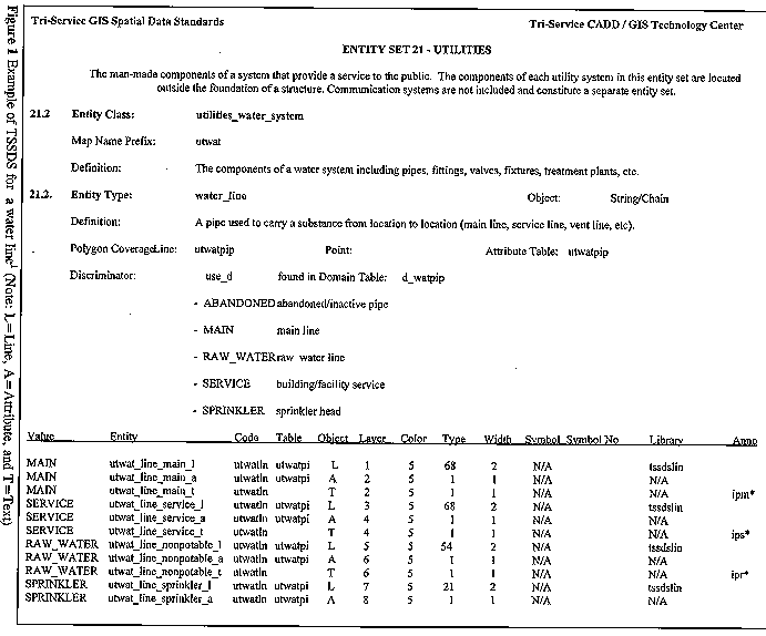
Example of TSSDS for a water line1 (Note: L=Line, A=Attribute, and T=Text)
Now that the composition of the DGN layout has been established, the conversion can be made based on the layer of the feature of interest. It is always easier to convert based on layer, especially if the features were captured by layer.
Given the DGN file structure, the DGN can be converted using the ArcInfo command IGDSARC at the ARC prompt. Below is the command usage for the IGDSARC command and related parameters:
Arc: IGDSARC <in_igds_file> <out_cover> {2D/3D} {xmin} {ymin} {xmax} {ymax}
{OVERLAP|INSIDE} {text_width}
Usages for this command are:
<in_igds_file> - name of IGDS file to be converted.
<out_cover > - name of the coverage to be created from the input IGDS file. The <out_cover> may contain any combination of points, lines, or annotation. An INFO file will be created name <out_cover>.ACODE, with the IGDS attributes in it. A optional binary system file called <out_cover>.alink will contain database pointers.
{2D/3D} - specifies if the IGDS file is two- or three-dimensional.
2D - refers to the two-dimensional IGDS file, which is the default.
3D - refers to the three-dimensional IGDS file.
{xmin}{ymin}{xmax}{ymax} - refers to the desired coordinate extent of the IGDS file to be translated.
The default is the full extent of the IGDS file, whereas IGDSINFO displays the x,y extent of the IGDS file.
{OVERLAP|INSIDE} - when x and y range is specified.
OVERLAP - all elements whose boundaries overlap the specified x,y range are extracted.
INSIDE - all elements whose bounding boxes are completely inside the specified x,y range are extracted.
{text_width} - width of the IGDS-TEXT item. The default will be 12 if no text width is given.
After the IGDSARC command is entered, a dialog box appears and prompts the user for the IGDS-to-ARC parameters. Below is an example of the dialog box:
Enter layer names and options (type END or $REST when done)
=============================================
Enter 1st layer and options:
Enter 2nd layer and options:
Enter nth layer and options:
When done entering the layers and options, type END or enter to end entering layers and options.
Below is the usage for the dialog box:
<layer_name|END|$REST><level><color><line_style><line_weight><element type> <cell_name><option_1...option_n>
Wildcards ( * ) can be used in place of these responses. The wildcard indicates that all the elements associated with the chosen element will be translated provided they meet the extraction criteria. Note: the user cannot leave empty fields; an integer or wildcard must be used.
The usage is broken down into the following options:
<layer_name|END|$REST> - layer description.
layer_name - user defined
END - ends layer input.
$REST - allows the user to take all remaining layers that have been previously specified. It must be the last layer specified, END is not needed. If $REST is not specified, the remaining layers will not be converted. To convert ALL element types and include them in one coverage, use the ALL option onto $REST. Example: $REST ALL.
<level> - levels range between 1 and 63.
<color> - colors range between 0 and 255.
<line_style> - line styles range between 0 and 7.
<line_weight> - line weights range between 0 and 31.
<element_type> - element types range between 1 and 127. Only eleven types of elements are translated by the IGDSARC command.
{cell name} - there must be an entry here if the element type is 2; otherwise the field should be blank. If the $REST ALL option is used, no entry needs to be made; the cell will be translated to arcs.
{option_1...option_n} - the amount of options entered is user dependent.
The next step after converting the DGN into a coverage is to build topology. The user must determine whether the feature converted is a polygon, point, or arc (line). In this case the TSSDS determined the feature type, coverage name, and what directory the coverage was stored in. The authors were at first skeptical on the data conversion process. However, after translating approximately 15 design files into approximately 40 coverages, it was determined that the use of any standard accelerates the translation process, as well as minimizing the frustrations of the conversion process.
The result from execution of the IGDSARC command is an INFO file named <out_cover>.ACODE4, which holds the graphic attribution codes from the IGDS design (DGN) file. These codes can be used to perform relates and joins to other feature attribute tables. The ACODE file also contains the graphic attribution code called IGDS-TEXT. IGDS-TEXT is where the feature attribute annotation is stored. The user can build topology for this annotation and use it to annotate the ArcInfo coverage in ARCEDIT.
LESSONS LEARNED
If the user desires to maintain the database linkages, the DGN file needs to be connected to the database through a schema. Without the schema setup, ArcInfo will not convert the connectivity. If the user copies the DGN from its parent directory, the user still needs to set up a schema. The WES-IAMP DGN files used in this effort were copied from their parent directory. We were unable to access the schema information. If the schema is present, an INFO file will be created,4 <cover>.alink, and will contain database pointers. This file type, <cover>.alink, is the key to linking a converted coverage in ArcInfo to an external database. To perform relates and joins to other feature attribute tables, this table must be created. The user can check to see if this file was created correctly by selecting it in INFO. With the <cover>.alink selected, the number of files that were selected should be examined. If this number is less than the number of features in the coverage, then there is a problem. Chances are the database schema was not setup properly in MicroStation. Other possible explanations are that the DGN was moved as described above or the DGN file could be corrupted.
REFERENCES CITED
1. Tri-Service CADD/GIS Technology Center, "The Tri-Service Spatial Data Standards, Release 1.6," 1996. U.S. Army Waterways Experiment Station, Vicksburg, MS.
2. Riegelmann, Katherine, James Hoff, and Edward Riegelmann, "DATA CONVERSION: The Conversion of MicroStation Cells to ArcInfo Symbology," 1996. Proceedings of the 16th Annual Esri User's Conference, Esri Inc., Redlands, CA.
3. Bentley Systems, Inc. and Intergraph Corporation, "MicroStation 2D Graphics Level 1, Course Guide," 1994. MicroStation is a registered trademark of Bentley Systems, Inc. IGDS is a trademark of Intergraph Corporation.
4. Environmental Systems Research Institute, Inc., "On-Line Documentation: ARC; ArcInfo release 7.0.4," 1995. ArcInfo is a registered trademark of Esri Inc., Redlands, CA.
5. Kreis, Bruce D., "ArcInfo Quick Reference," 1995. OnWord Press, Santa Fe, NM.
RELATED READING MATERIALS
1. Montgomery, Glenn, and Harold Schuch, "GIS Data Conversion Handbook," 1993. GIS World Books, Fort Collins, CO.
2. Star, Jeffery, and John Estes, "Geographic Information Systems: AN INTRODUCTION," 1990, Prentice Hall, New York, NY.
3. Aronoff, Stan, "GEOGRAPHIC INFORMATION SYSTEMS: A Management Perspective," 1989, 1991, WDL Publications, Ottawa, Canada.
ACKNOWLEDGMENTS
Special thanks to the Tri-Service CADD/GIS Technology Center for their support of this paper and presentation. In particular, the authors appreciated the assistance of Mr. Chip Fleming at the Tri-Service Center in creating the TSSDS figure; and to Kathy and Edward Rieglemann with their previous collaboration on data conversion methods.2