Bi-Directional Data Converter of IHO S57
S57 is a standard defined by the International Hydrographic Organization (IHO)
for the exchange of digital hydrographic data. It was finalized on November,
1996. A bi-directional data converter has been developed to import S57 data
into ArcInfo format and to export ArcInfo data into S57 format. This paper
discusses the mapping of S57 data model to the ArcInfo data model and the
software architecture of the data translator. The goal of this paper is to
provide information that will help the user use the translator successfully.
The S57 data model
The S57 data model takes an object-oriented approach toward the modeling of
hydrographic data. Each real-world entity is described by an object that
belongs to a certain class. Each object has a set of attributes associated
with it. As shown in the figure 1, there are two kind of objects:
feature objects and spatial objects.
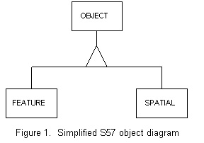
The feature object is used to describe a real-world phenomenon like a
beacon, a buoy, a land area, a sea area, and so on. A spatial object is used
to represent a location on earth surface like a point (which is called an
isolated node in S57 data model) with its latitude
and longitude coordinates. A feature object will use a spatial object to
indicated its location. Both kinds of objects have attributes associated
with them. For example, a beacon object will have attributes like color; a
spatial object, say an isolated node, will have attributes like positional
accuracy. These two kinds of objects are the conceptual building blocks of
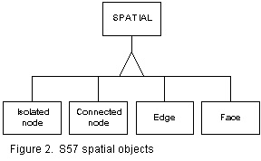
a dataset (which is called a cell in the S57 standard). Currently there are
four types of spatial objects (see figure 2). They are isolated nodes,
connected nodes, edges and faces. Detail definitions of these spatial
objects can be found in the S57 standard.
S57 topology
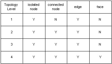
The S57 data model supports four topology levels: cartographic spaghetti
(level 1), chain-node (level 2) topology, planar graph (level 3) topology
and full topology (level 4). Each topology level supports a certain set of
spatial objects.
In cartographic spaghetti (level 1 topology), only isolated nodes and edges
are allowed in the cell. Edges may cross itself or other edges without
being broken. Duplicate edges are also allowed. An area is formed by a set
of edges that when assembled forms it's boundary.
In Chain-node (level 2) topology, isolated nodes, connected nodes and edges
are allowed in the cell. Each edge must start and end with a connected node.
Edges may cross themselves or other edges without being broken. No duplicate
edges are allowed. An area is formed by a group of edges that describe its
boundary.
Planar graph (level 3) topology is very similar to chain-node topology
except that all edges must meet at connected nodes, that is edges may not
cross themselves or other edges without being broken.
Full (level 4) topology is the highest topology level , and face objects
are allowed to exist in the cell to represent areas. All conditions (except
that areas are represent by faces instead of sets of edges) for planar graph
topology are still true for level 4 topology.
Table 1 summarizes the relationship between spatial objects and topology level
Note: currently only one product specification (for the Electronic Nautical
Chart or ENC) exists in S57 standards and it uses chain-node topology. However,
the translator supports all topology levels for use in future product
specifications.
The S57 object catalogue
The S57 standard provides a standard object catalogue that specifies classes
of objects. Data encoders can use the catalogue to depict hydrographic data.
In version 3 of the S57 standard, 181 object classes are defined. Each class
has a set of attributes associated with it. The object catalogue also
provides attribute definitions including attribute data types and valid value
domains. The vital information in the object catalogue is stored in a
database within the translator. The translator is aware of the relationship
between each object and its attributes. Hence, during import and export, only
the attributes applicable to the object will be manipulated.
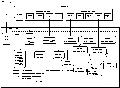
Mapping between the S57 and ArcInfo data models
Spatial objects. As described before, there can be at most four types of
spatial objects in a cell. Each type of spatial object will map to an
individual ArcInfo as follows:
- Each isolated node will map to one record in an ArcInfo point attribute
table (PAT).
- Each Connected node will map to one record in an ArcInfo node attribute
table (NAT).
- Each edge will map to one record in an ArcInfo route subclass called vename
(ROUTE.VENAME).
- Each face will map to one record in an ArcInfo polygon attribute
table (PAT).
To resolve the name conflict between the point and polygon attribute
tables. The translator saves all isolated nodes in a separate ArcInfo
coverage and adds a "_P" prefix. For example, if a S57 object file
US1000001.000 contains both isolated nodes and (faces or feature
area objects), two ArcInfo coverages are created, namely US100001
and US100001_P.
Feature objects are separated by object code or object label (i.e. class)
but the S57 standard does not segregate features by their spatial
primitives. However it make sense to do this type of classification for
data organization purposes. Thus, the translator divides feature objects
by both their class name and their spatial representations. The following
paragraphs explain how feature objects are mapped into ArcInfo.
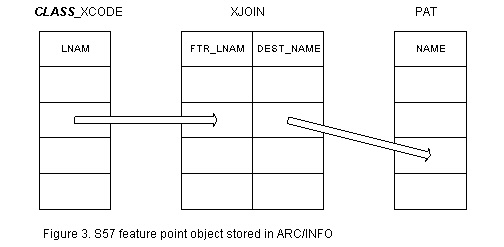
Each feature point object will map to a record in the xcode INFO table for
that class. The relationship between the feature point object and its
spatial primitive (i.e., the isolated node stored in the PAT) is captured
by a record in the xjoin INFO table (figure 3).
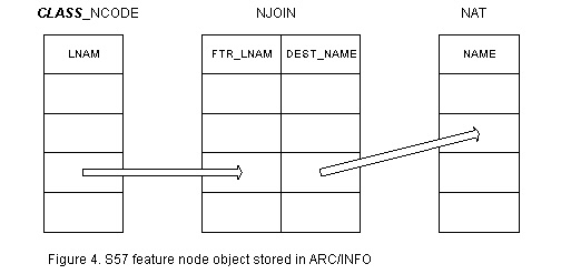
Each feature node object will map to a record in the ncode INFO table for
that class. The relationship between the feature node object and its
spatial primitive (i.e., the connected node stored in the NAT) is captured
by a record in the njoin INFO table (figure 4).
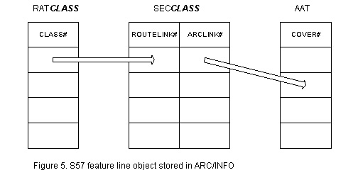
Each feature line object will map to a record in the ArcInfo route
subclass for that class. The relationship between the feature line object
and its spatial primitive (i.e., edge) will be maintained by the section
INFO table (figure 5).
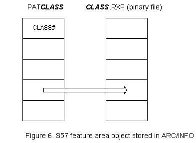
Each feature area object will map to a record in the ArcInfo region
subclass for that class. The relationship between the region and it's
spatial primitive (i.e., edge / face ) will be maintained by binary files
such as rxp and pal (figure 6).
Each complex feature will map to a record in the ccode INFO table for
that class. The relationship between the complex feature area and it's
target feature objects or target spatial objects are stored in the cjoin
INFO table (figure 7).
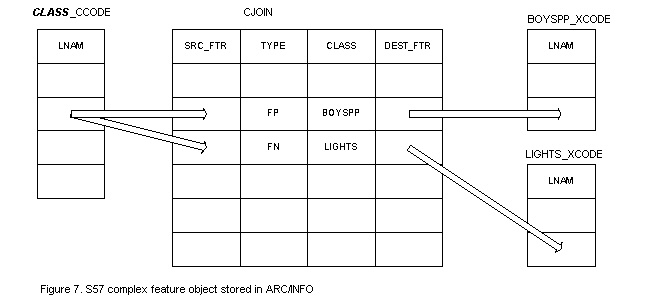
Figure 8 summarizes the mapping of all of the S57 objects and ArcInfo entity.
Software architecture
During the design phase of the translator, the software designer chose to
use a layered approach toward building the software. The translator follows
a model similar to the OSI or TCP/IP protocol stack model. There are several
layers of software. Each layer is self-contained and provides a service
to the layer above it. The layers closer to the bottom of the stack perform
primitive (low level) operations like handling bits and bytes of data. The
layers closer to the top of the stack operate on a higher level that is much
closer to the user's view of the data. The layer model has been used for
several data handling software architectures and it has proven to be
effective and successful. It offers several advantage including , but not
limited to, data abstraction, modular design, extensibility, and
maintainability. The following figure shows the software layers for the data
converter.
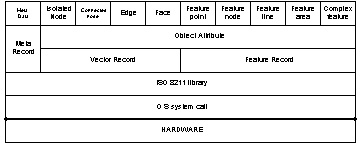
Data abstraction
The layer approach gives the software developer the
methodology for closely modeling the S57 standard. As we all know,
digital data consists of bits and bytes recorded on a media such as CD-ROM,
disk file, tape, and so on. S57 standard chose to use the ISO8211:1994
standard to define the actual encapsulation mechanism. The fundamental
job of the translator is to extracted the bit and byte and then assemble a
ISO8211 records out of it which is the precise job description of the
ISO8211 library layer. Thus the layers above it does not need to know
any system call used to extract bit and byte from the media. It operates
strictly on ISO8211 records only. These layers , namely meta record, vector
record, and feature record, will issue request to the ISO8211 library
layer for a specific type of record. For example, the vector record layer
will ask for all ISO8211 vector records. If the current vector record
being worked on is an isolated node, vector record layer will passed it
to the object attribute layer for attribute extraction and then to the
isolated node layer for geometry conversion.
Modular design
Once these layers are defined, each module can be designed
and even implemented at the same time because the design choices and
implementation details within each module do not affect other modules.
The only linkage between the lower level and the upper level layers is
the interface between them. As long as the interface remains the same,
each module is free to implement its functions in the most natural and
efficient manner.
Extensibility
The layer approach allow software to be extended and
expanded in logical ways. For example if is a new spatial object type is
introduced, the change to the software will be localized to the module
that handles vector records and a new module will be added at the same
level as used for other spatial objects. No other modules will be affected
at all.
Maintainability
Software maintenance might not be the favorite of task
of a programmer, simply because it is difficult. The layer approach
alleviates the maintenance burden by isolating the activity within a
particular layer. Debugging the code for a layer is easier than debugging
the software for the whole translator because the amount of code that
needed to be examined is much smaller. Enhancements to the software can
be done in a layer-by-layer fashion too. First identity the layer that
contains the bottleneck; then a new algorithm and/or data structure can
be deployed to increase performance. Again the implementation within a
layer does not affect the other layers as long as the interface between
them is consistent. Enhancement for a layer also usually results in less
code change, thus the possibility of introducing new bug is minimized.
Conclusion
This paper presents a brief review of the S57 data model. It also
discusses the mapping between the S57 objects and the ArcInfo entity
and the software architecture of the converter. I hope the information
being presented in this paper will help users gain more knowledge
about the data converter and will assist them in the future to use
the software more successfully.
REFERENCES
International Hydrographic Organization, IHO TRANSFER STANDAND for DIGITAL HYDROGRAPHIC DATA. Special Publication No. 57. Edition 3.0 Nov., 1996.
International Organization for Standardization, Specification for a Data Descriptive File for Information Interchange. ANSI/ISO/IEC 8211-1994.
Pui S. (Ivan) Cheung
Software Analyst/Programmer,
Defence Service, Application Division,
Environmental System Research Institute
380 New York Street,
Redlands, California 92373-8100
Telephone: (909) 793 2853
Fax: (909) 793 5953
icheung@Esri.com

