Bechtel Nevada operates and flies Daedalus multispectral scanners for funded project tasks at the Department of Energy's Remote Sensing Laboratory. Historically, processing and analysis of multispectral data has afforded scientists the opportunity to see natural phenomena not visible to the naked eye. However, only recently has a system, more specifically a Geometric Correction System, existed to automatically geo-reference these data directly into a Geographic Information System database. Now, analyses, performed previously in a non-geospatial environment, are integrated directly into an Arc/Info GIS. This technology is of direct benefit to environmental and emergency response applications.
GIS Meets Airborne MSS:
Geospatial Applications of High-Resolution Multispectral Data
Albert Guber
GIS Analyst/Manager
USDOE Remote Sensing Laboratory
Presented at:
1999 Esri User Group Conference
San Diego, CA
July 27, 1999
ABSTRACT
Bechtel Nevada operates and flies Daedalus multispectral scanners for funded project tasks at the Department of Energy's Remote Sensing Laboratory. Historically, processing and analysis of multispectral data has afforded scientists the opportunity to see natural phenomena not visible to the naked eye. However, only recently has a system, more specifically a Geometric Correction System, existed to automatically geo-reference these data directly into a Geographic Information System database. Now, analyses, performed previously in a non-geospatial environment, are integrated directly into an Arc/Info GIS. This technology is of direct benefit to environmental and emergency response applications.
The U.S. Department of Energy�s (DOE) Remote Sensing Laboratory (RSL) operates a Daedalus Multispectral Scanner (MSS) to support environmental, emergency response, and other funded project work. The Daedalus 1268 scanner is a passive, electro-optical sensor designed to collect and record reflected or emitted electromagnetic radiation. The system separates the radiation into 12 distinct spectral bands from the visible region through the thermal infrared. The RSL acquires scanner data to support a wide range of missions including environmental change detection, vegetation stress detection, vegetation classification, and search applications. Until recently, MSS scanner applications were performed almost entirely in a non-georeferenced pixel coordinate scheme. Due to the extreme and irregular distortion associated with airborne scanner imagery, almost all analyses were performed in commercial image processing packages and not referenced to Geographic Information System (GIS) data sets. With the advent of high speed computers and on-board aircraft attitude recording devices, RSL has developed a Geometric Correction System (GCS) for airborne scanner data that allows for correction to multiple levels of geographic accuracy. Now, traditional applications associated with the Daedalus scanner are integrated directly into the GIS environment and fused directly with traditional GIS vector and raster data sets.
The Scanner
The Daedalus MSS is a passive electro-optical sensor designed to collect and digitally record reflected or emitted electromagnetic radiation from an aerial platform. The scanner separates the radiation into spectral bands between the visible and thermal infrared region of the spectrum. The scanner system consists of a scan head, spectrometer, digitizer, operator console, hard-drive data recorder, and a power distributor/reference source. The scanner can be configured to incorporate a detector designed for coastal zones or to operate as a narrow-band Short-wave Infrared (SWIR) imaging spectrometer. The RSL flies the scanner on fixed-wing aircraft or helicopters depending on mission requirements for the particular acquisition. Acquisition altitudes range from 43,000 to 250 feet with subsequent ground resolutions of 30 meters and 4 inches, respectively. Most data acquisitions to date, and those referenced in this paper, are collected in the scanner�s SWIR configuration. In this mode, the scanner collects 12 channels of data broken down into six visible bands, 2 reflected near infrared (NIR) bands, 2 reflected SWIR bands, and two emitted thermal infrared (IR) bands. The band wavelengths are:
Channel 1 .42-.45 micrometers
Channel 2 .45-.51
Channel 3 .51-.59
Channel 4 .58-.62
Channel 5 .61-.66
Channel 6 .65-.73
Channel 7 .71-.82
Channel 8 .81-.95
Channel 9 1.6-1.8
Channel 10 2.1-2.4
Channel 11 8.2-10.5
Channel 12 8.2-10.5
The Applications
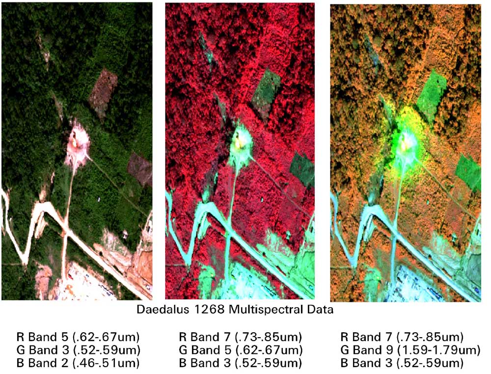
At the RSL, scientists have been using data from the MSS to address various aspects of environmental and Emergency Response applications for many years. Due to the unique characteristics of both spectral and spatial components of airborne MSS data, much work has been done in the areas of environmental vegetation stress detection, seep detection, buried object detection, and change detection. Vegetation stress detection leverages on the SWIR bands and their ability to differentiate small changes in chlorophyll content of leafy vegetation biomass. These changes are not evident in the visible, NIR, or thermal bands. As a result, the SWIR channels can often provide detection of areas of mild stress before longer-term irreversible problems occur. Figure 1 shows an example of a study in which vegetation stress is much more visible in the SWIR bands than in the NIR and visible. The example shows the area around a natural gas flare and its apparent effect on the surrounding vegetation.
Figure 1 Vegetation stress from a natural gas flare.
Seep detection applications use the SWIR bands as well as the thermal IR. The SWIR again indicates stressed vegetation as a result of either excessive water or contamination. The thermal IR picks up subtle temperature differences due to changes in soil moisture content in and around a seep location. Figure 2 illustrates an analysis in which seeps were detected. These data could be used to plan for containment and routing of underground water sources in the area.

Figure 2 Detection of Seeps
Buried object detection again leverages the SWIR as well as high spatial capabilities to detect areas in which surface vegetation is stressed or has been disturbed. Figure 3 shows a study in which objects were buried at various depths and carefully covered to show minimal visible surface disturbance. Note that all objects were easily detected using the MSS scanner imagery. This has direct use in detecting burial areas or individual drums of waste for environmental applications.

Figure 3 Detection of Buried Objects
As demonstrated above, the unique characteristics of the scanner lend themselves well to detection of vegetation stress and related environmental applications. The scanner also has direct applicability to several emergency response applications. To support forest fire management, thermal imagery collected by the scanner can be reviewed real-time on-board the aircraft to map both the extent of the active fire as well as burn areas. The real-time analysis can also quickly route firefighters on the ground to hot spot targets within the fire area itself. Also, the reflected wavelengths of the scanner can be used to map soil/vegetation moisture to help predict the most likely path of the fire in the future. Similarly, the scanner can be used to support oil spill disasters by providing capabilities for slick detection, mapping, and monitoring using both the thermal and ultraviolet bands. If a spill results from a pipeline rupture, the scanner�s thermal bands can be utilized to help locate ruptures and map oil flows and environmental impacts. The scanner can support activities such as search and rescue for airplane accidents or damage assessment from hurricanes or earthquakes by optimizing the multispectral characteristics of the scanner. In the event of a plane accident, the system can be flown to search for missing pieces of wreckage or debris that might lend further insight to an accident investigation. Infrastructure damage such as ruptured pipelines, water mains, and other liquid transport systems can be detected and monitored using the reflected and emitted bands of the scanner.
Geometric Correction System1
A critical requirement for the entry of remote sensing data into a GIS is that the data be spatially referenced to a common datum and projection. Although distortions of space-based multispectral scanners have been acknowledged and well characterized in the literature, distortions caused by fixed-wing and helicopter-based airborne systems have not been as widely reported. Errors inherent in an airborne system result from changes in aircraft altitude and attitude caused by the surrounding turbulent atmosphere. As the mirror in the line scanner rotates and acquires multispectral data, additional distortions are recorded. These distortions vary with the angle of the mirror from nadir and the topography of the portion of the earth being imaged at that instant. Figure 4 is an example of raw data with such distortions.
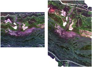
Figure 4 Raw data with distortions (left). Corrected data (right).
Although it is relatively easy to characterize the correction required for any single distortion, the problem is the additive nature of the multiple distortions caused by the continuous aircraft motion through the atmosphere. For the past five years, the RSL has been developing and testing a GCS for removing these distortions. The system is used successfully to correct Daedalus 1268 multispectral data acquired with various airborne platforms. Aircraft position is established using a differential Global Positioning System (GPS). One (rover) receiver is placed in the aircraft and a second (master) station is placed at a known or surveyed location on the ground. Aircraft orientation is determined by a Litton LN-200, a lightweight Inertial Measuring Unit (IMU) based on a triad of fiber optic gyros and silicon accelerometers. The TrueTime encoding system provides a timestamp to synchronize the position and orientation data with the MSS data. The IMU and timing information, as well as the GPS receiver data, is recorded for processing once the aircraft has landed. The timing information is also recorded into the Daedalus 1268 housekeeping data for each line. At the same time, GPS information is recorded. The ground processing element uses RSL-developed software to process the IMU data (GCSProcess) and commercial-off-the-shelf software to differentially process the GPS data (GrafNav), blend the IMU and GPS solutions (PosProc), and finally geometrically correct the data. The GCS produces corrected MSS imagery at three levels of precision. These levels are a combination of corrections for platform variation (pitch, roll, yaw, altitude), topography using a digital elevation model (DEM), and rectification to map accuracy.
Level 1 GCS: Scanner imagery is corrected for high frequency platform variation, but positional accuracy with respect to map coordinates is not guaranteed.
Level 2 GCS: Scanner imagery is corrected for platform variation and referenced to a datum and projection. The topographic correction is applied using a DEM.
Level 3 GCS: Scanner imagery is corrected for platform variation and topography and referenced to a datum and projection. The topographic correction is applied using a high-resolution DEM. The scanner imagery is then rectified to an orthophoto and can be mosaicked, if required. This technique uses standard numeric processing techniques and requires the selection of 15-20 ground control points.
The integration of the GCS into scanner missions allows scientists at the RSL to perform very accurate spatial analyses using the unique spectral capabilities of the instrument. Now, it is possible to perform temporal change detection analyses from the airborne scanner data with a high level of confidence. The usefulness of airborne multispectral data has been exploited in traditional image processing projects at the RSL for many years. The advent of the GCS now brings together these applications with the suite of geo-processing tools that GIS technology affords. GIS analyses, formerly performed using satellite imagery or digital orthophotos, are now performed using the high spatial and spectral resolution of Daedalus scanner data. The integration of GIS and airborne scanner data is proving to be a powerful new tool for both environmental and emergency response applications.
REFERENCES
1 S.B. Brewster, Jr., Geometric Correction System: Capabilities, Processing, and Applications, DOE/NV1178--315, Bechtel Nevada, (1999).
ACKNOWLEDGMENTS
This work was performed by Bechtel Nevada for the U.S. Department of Energy, Nevada Operations Office, under Contract No. DE-AC08-96NV11718.
By acceptance of this article, the publisher and/or recipient acknowledges the U.S. Government's right to retain a nonexclusive, royalty-free license in and to any copyright covering this article.
This report was prepared as an account of work sponsored by an agency of the United States Government. Neither the United States Government nor any agency thereof, nor any of their employees, nor any of their contractors, subcontractors or their employees, makes any warranty, express or implied, or assumes any legal liability or responsibility for the accuracy, completeness, or any third party=s use or the results of such use of any information, apparatus, product, or process disclosed, or represents that its use would not infringe privately owned rights. Reference herein to any specific commercial product, process, or service by trade name, trademark, manufacturer, or otherwise, does not necessarily constitute or imply its endorsement, recommendation, or favoring by the United States Government or any agency thereof or its contractors or subcontractors. The views and opinions of authors expressed herein do not necessarily state or reflect those of the United States Government or any agency thereof.