Jeffrey B. Miller and John Onwuteaka, PhD
Oil
Spill Emergency Response GIS.
Using GIS to Model Environmental Vulnerability in
Coastal Oil Fields, East Central Nigeria.
The
potential vulnerability of the landscape to oil spills is an information base
critical to petroleum industry emergency response planners. In an emergency
event, information on the potential risk for oil spills and the sensitivity of
landscapes to oil spills is required. Tools for rapid production of response
information are paramount.
Earth
Satellite Corporation (EarthSat) worked with Delta Systematics to evaluate the
environmental vulnerability of the landscape to oil spills within the oil fields
in the east central area of coastal
Nigeria. EarthSat used ARC/INFO GRID to model the potential risk of oil spills
from existing oil facilities and refined hydrocarbon shipping lanes. GRID was
also used to synthesize landcover classifications from digital Landsat TM
imagery and digitized maps to model the sensitivity of the regional environment
to oil spills. The project also
modeled response time for air- and sea borne response teams to potential accident
sites.
The
resulting models were integrated into ArcView GIS for interactive display, query
and analysis by emergency response planners. This ArcView project, using the
Spatial Analyst extension, is a simple and powerful tool for emergency planning
and response in this region.
Oil Spill Emergency Response GIS.
Using
GIS to Model Environmental Vulnerability in Coastal Oil Fields,
East Central Nigeria.
Project Goals
Earth Satellite Corporation and Delta Systematics developed a qualitative GIS tool to address a number of geographic questions concerning oil spill hazard within a pilot study area of coastal east central Nigeria. The project was undertaken to develop initial assessments of :
- The pattern of the risk of petroleum spills.
- The sensitivity of the landscape to the risk of petroleum spills.
- Vehicular emergency response times to petroleum spills.
- Emergency response times to high sensitivity areas.
- The sensitivity of areas to oil spill mitigation efforts, including spill caching.
Methods
Study Area
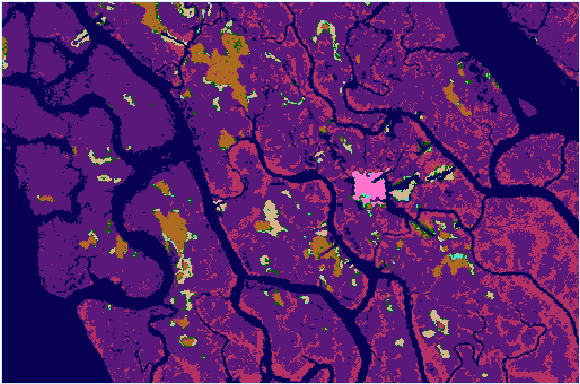
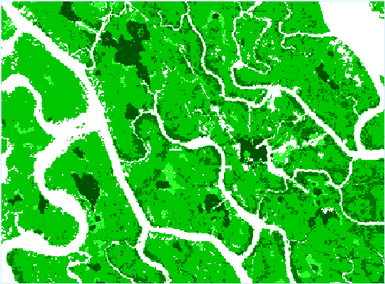
The project study area is a coastal tidal flat in southern Nigeria approximately 84 km sq. or 32 mi sq. in area. Major features include a petroleum central flow station, gas and oil pipes and well heads. Tidal waterways serve in effect as a transportation network. Landcover is dominated by mangrove peat flats and freshwater forest banks, and regrowth mangrove flats. The landcover depicted above is derived through a multispectral analysis of Landsat TM imagery, Late December 1986.
Tools
Esri Arc/Info 7.2.1 GRID (SUN Solaris) was the primary analysis software. Modeling was implemented through Arc/Info AML scripting. ArcView 3.1 with the Spatial Analyst Extension for Windows98 was used for cartography and query. EarthSat's Sun Enterprise 4000 Server, along with an Intel Pentium 133 PC running PC-Xware X-Terminal Emulator were the primary hardware resources for the project.
Risk Surfaces
The project identified petroleum spill
risk/hazard from:
- Well heads
- A central flow station facility
- Marine/Riparian-based transportation
- Gas & Petroleum Pipelines
The project took a risk maximizing approach,
i.e., it identified the maximum relative risk for each criteria and aggregated
them.
The project was an attempt to qualify rather than quantify risk. The cost of oil migration from each criteria (well heads, flow station, marine oil transport, and gas/oil pipelines) was identified. The cost was then transformed into a risk surface for each criteria. These risk criteria were merged into a single aggregate risk layer.
The Costdistance function is supported in both GRID and ArcView. It is an appropriate tool for modeling migration through an impedance field. The models treated risk as a translation of cost. The lower the cost of migration of oil through the landscape, the greater the risk of hazard.
Oil Migration Impedance Surface
Landcover and planimetric information was used to generate a friction or impedance surface that adjusts the cost of migration of oil through the landscape. For example, swamp forest and dredged spoils were given higher friction values (shown in deep reds above), while water, sand and cut banks are given a lower friction value (illustrated in white and light red tones). The costdistance function used the oil migration impedance surface as an input cost grid.
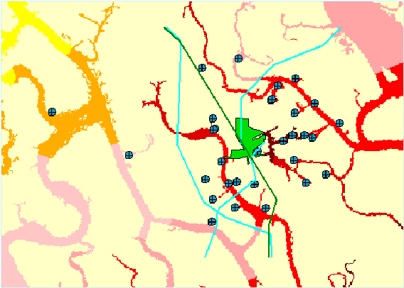
Wellheads Risk Surface
Risk of exposure to oil spill stemming from wellheads is modeled as a function of cost of transport of oil across the landscape from oil wellheads. The model uses landcover and planimetry information to determine impedance to oil transport across landscape. It identifies for each cell the weighted accumulative cost of transport of oil across the landscape from the nearest source wellhead. The above image depicts the derived risk surface, with wellheads shown in crossed circles. The map portrays higher risk areas in darker reds, while lower risk areas are shown in light reds.
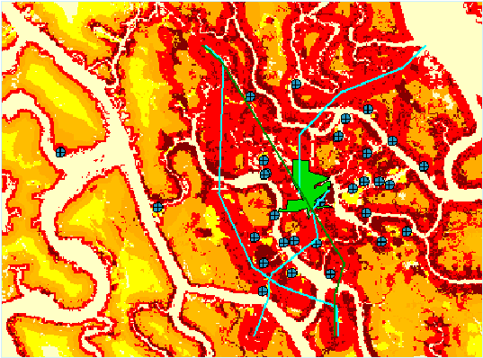
Central Flow Station Facility Risk Surface
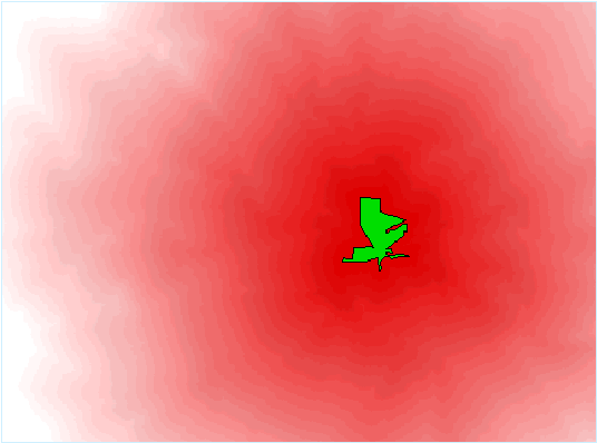
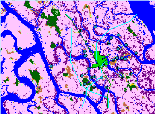
The central flow station is a control station for petroleum processing (represented in green above). Risk of oil spills from this facility is fundamentally higher than from well heads given that most petroleum in the area will be routed here. The cost of transport from the flow station was modeled as 1/3 that of migration from wells. This reflects a fundamental source of higher risk. Greater risk areas are symbolized in deeper tones of red.
Shipping Lanes Risk Surface
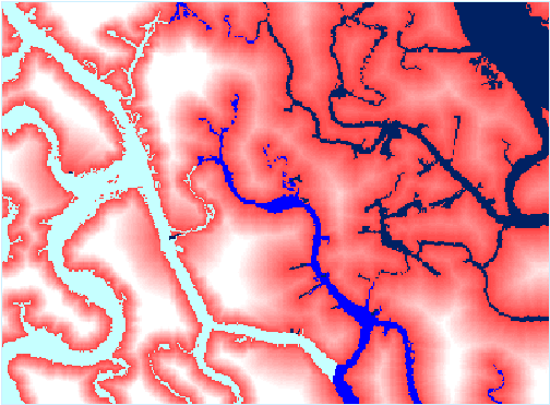
The shipping lanes risk surface represents the risk of oil spill from maritime-based petroleum transport. The stream network in effect acts as a transportation network for oil barges and tankers throughout the study area. These rivers were categorized into three levels of petroleum transportation volume : low, moderate and high. The low transportation volume is symbolized in light blue in the above image. Moderate volume transportation lanes are symbolized in medium blue, while the high volume transportation lanes are shown in dark blue.
The cost of oil migration from high volume shipping lanes is modeled to be 1/3 of that for risk from well heads. The cost of oil migration from moderate volume shipping lanes is 1/2 of that for risk from well heads. Lastly, the cost of oil migration from low volume shipping lanes is 3/4 of that for risk from the well heads. The above image clearly illustrates that greater risk (symbolized in darker reds) exists in areas proximate to highest volume shipping lanes.
Gas and Petroleum Pipelines Risk Surface
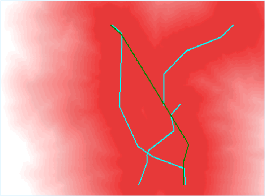
Gas and petroleum lines (shown as blue and green lines respectively above) represent the most significant source of risk of petroleum spill in the study area. The cost of oil migration from pipelines through the friction surface is modeled to be one fifth that of wellheads cost. This reflects the continuous flow (and high risk) of oil and gas through these networks. Darker reds symbolize greater risk of oil spill.
 |
 |
The minimum cost of oil transport for each layer in overlay is identified, and merged into a single layer. This has a risk maximizing effect : the greatest exposure to oil spill risk across all risk sources is mapped on a single surface. The cost is then partitioned into risk categories, lower cost representing higher risk, and higher cost representing lower risk. Cost is weighted by source type: pipelines and shipping lanes represent the greater portion of risk, while the central station and wellheads are qualitatively lower risk factors. The result is a synthesis of all sources of oil spill risk to a single surface. This surface addresses our first goal of identifying the pattern of oil spill risk throughout the study area.
Vulnerability
Vulnerability is modeled as a suitability surface. Vulnerability is the interaction of aggregate risk of oil spills with an Environmental Sensitivity Index (ESI) surface. It is an attempt at characterizing the significance of the risk of oil spill to the landscape. Vulnerability may be expressed as the following formula : Vulnerability = Risk Surface x ESI Sensitivity
Environmental Sensitivity Index (ESI) Surface
The Environmental Sensitivity Index (ESI) is a weighted landscape sensitivity surface based on landcover, land use and planimetry. For example, areas that are extremely sensitive to oil spills, such as freshwater swamp forests, receive high sensitivity scores. Areas of importance to human use, such as economic activity (e.g., amenity beaches) also receive high sensitivity scores. Areas of high sensitivity are symbolized above in dark tones of green. Areas of higher resistance to oil spills, or areas that already have been affected by significant human use (e.g., cut banks) receive lower sensitivity scores. Lower sensitivity score areas are symbolized above in light green tones. This surface meets the project goal of mapping the sensitivity of the landscape to the risk of petroleum spills.
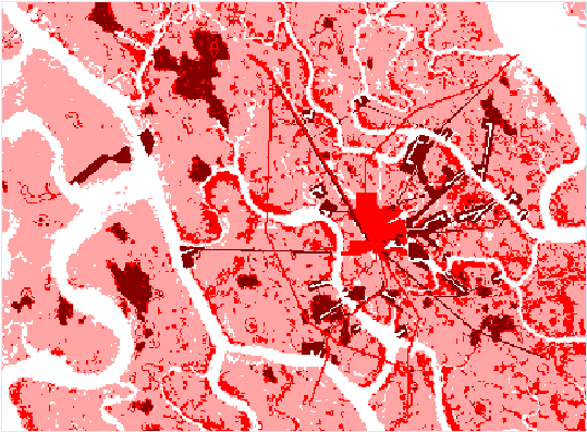
The Vulnerability Surface
As stated earlier, the aggregate risk surface and the Environmental Sensitivity Index are combined in multiplication to produce a surface of continuous vulnerability. The highest vulnerability areas tend to be coastal, proximate to wellheads and oil pipes. Swamp forests, beaches and mangrove forests near facilities also tend to have higher vulnerabilities. The darker orange/red tones represent these high vulnerability areas. Areas on lighter, pale yellows tend to be features that have low risk to oil spills, are distant from oil facilities, and have lowest sensitivity to oil spills. This map addresses the goal of identifying landscape vulnerability to oil spills throughout the study area.
Vehicular Emergency Response Estimates
EarthSat and Delta Systematics also modeled air- and sea borne vehicular emergency response times to the study area. The resulting surfaces give an immediate overview of the approximate time required to reach any location within the study area using either helicopter or boat. The resulting emergency response times can be easily overlayed with risk, sensitivity, and vulnerability surfaces to determine travel times to high vulnerability areas in the event of an oil spill.
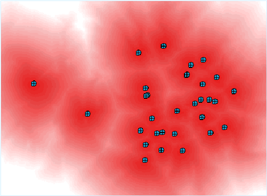
Helicopter Emergency Response Time
Helicopter emergency response time assumes a straight path of flight at 60 mph from the helicopter pad (north and west of the study area) to the emergency site. The model uses the eucdistance grid function to identify linear travel times from the helicopter pad to each cell in the study area. The resulting image above portrays estimated helicopter emergency response time. For instance, areas in yellow, in the northeast section of the map, could be reached in approximately seven to eight minutes. Areas in darker reds could be reached in approximately twelve or more minutes.
Watercraft Emergency Response Time
The watercraft response time model assumes watercraft travel at 45 mph through riverine areas only. The model uses the costdistance function to identify riparian travel times from the boat dock (north and west of the study area) to each river cell in the study area. In the image above, watercraft response time is represented in five-minute travel time intervals. For example, areas in bright yellow can be reached in approximately twenty-five to thirty minutes. Areas in pink tones can be reached in approximately thirty-five to forty minutes. Areas in dark red can be reached in fifty-five or more minutes.
Results
Hardcopy maps and an ArcView project were produced to present the results of the pilot study.
Hardcopy Maps
Environmental Sensitivity Index (ESI)
Shoreline Type Map
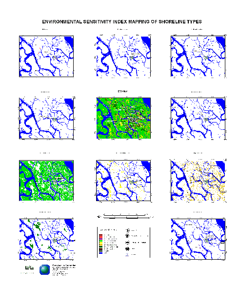
The Environmental Sensitivity
Index (ESI) Shoreline Type Map portrays
sensitivity features throughout the study area. It is a useful tool for
portraying the uniquely sensitive features within the area, such as fish
nurseries, fisheries, and bivalve habitat.
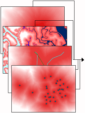
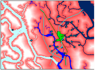
Analysis Process Map
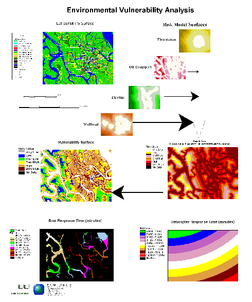
The Analysis Process Map shows the GIS modeling process used to produce the risk, vulnerability, and travel time surfaces.
ArcView Project

An ArcView 3.1 project was composed for query, analysis and mapping of risk, vulnerability to oil spills, and travel time surfaces. The project is also the primary means of delivering the product in digital format. ArcView, with the Spatial Analyst extension, was selected for a number of reasons : The end-user can interactively query travel times at a given point using the ArcView Identify tool. It is easy to generate aggregate statistics of sensitivity over a given area using the ArcView Summarize Zones tool. The user can find regional statistics of sensitivity using ArcView or neighborhood (focal) functions (e.g., focalsum). Lastly, it is easy to find the total sensitivity of the landscape for determining the potential suitability of a site for cleanup caching. This capability is especially important for addressing the project requirement of on-the-fly calculation of sensitivity when determining cache areas for oil spill cleanup.
Recommendations
Three recommendations for continued work on the coastal oil fields pilot project are forwarded here. Firstly, more detailed field work on facility capacity, oil shipping volume, and tidal patterns could be integrated to enhance the modeling efforts. Statistically calibrated surfaces would represent an improvement over the existing qualitative surfaces. Secondly, the pilot project models land-based sensitivity and vulnerability only. Inclusion of a water/riparian sensitivity function is needed. Lastly, a graphic user interface (GUI) for interactive modeling would simplify the process of developing a series calibrated models for the pilot area.
The authors wish to acknowledge Jacques Piou for his input and efforts in assisting in the design and implementation of this project.
Jeffrey B. Miller
Staff Scientist
Earth Satellite Corporation
6011 Executive Boulevard Suite 400,
Rockville, MD 20852-3804
(301) 231-0660
FAX (301) 231-5020
jmiller@earthsat.com
http://www.earthsat.com
John Onwuteaka
Director, Consultancy
Delta Systematics
36 Onne Road
G.R.A. Phase II
P.O. Box 4844
Port Harcourt, Nigeria
Tel 011 234 84 232 706
FAX 011 234 84 332 706
joteaka@infoweb.abs.net