
Applying GPS and ArcView GIS
to NPDES MS4
GIS Data Collection Application
Florida Department of Transportation
Turnpike District Contracted Project
Primary Contractor - University of Florida's GeoPlan Center
Subcontractor - GeoFocus Inc.
Authors
Renee Pfeilsticker
Suzanne Doty
Paul Zwick Ph.D.
| GeoPlan Center
431 ARCH Building P.O. Box 115706 Gainesville, FL 32611-5706 (352) 392-0997 renee@geoplan.ufl.edu paul@geoplan.ufl.edu |
|
Introduction
The University of Florida's GeoPlan Center, in association with GeoFocus Inc., is developing a complete Graphic Information System (GIS) program to meet the needs of the Florida Department of Transportation (FDOT) Turnpike District's National Pollution Discharge Elimination System (NPDES) Municipal Separate Storm System (MS4). The application will manage database development, inspections, data tracking, and reporting. The program incorporates two different methods of GIS baseline database development, utilizing a pen-tablet application with Trimble Pro XR and a Trimble data logger with Trimble Pro XR GPS unit. This paper will outline the two methods of GIS baseline database development, including project history, method development, pre-field and post-field collection procedures, field collection procedures, data dictionary development, importing data into the desktop application, and projection.
Turnpike NPDES MS4 History
The Turnpike District presently consists
of six different toll-ways running through 16 counties, three (3) cities
with populations over 250,000, seven (7) counties with populations over
100,000, four (4) FDOT Districts, three (3) water management districts,
and three (3) Department of Environmental Protection (DEP) Districts. The
Turnpike is continually building and acquiring additional toll-ways. Presently
the Turnpike is a co-applicant in nine (9) NPDES MS4 permits, with each
permit requiring slightly different compliance activities. In order to
simplify the Turnpike's NPDSES MS4 program all permit requirements were
combined into one composite requirement list, which are to be performed
in each permit area. This produced a uniform set of activities to be achieved,
tracked, and reported. In some permit areas more activities are performed
then required, allowing a less complex approach than tracking each permit
separately. In this way the permit activities can be reported in an all-in-one
annual report with a separate section for each permit.
NPDES MS4 activities overlap other permits held with the water management districts or DEP. To reduce any duplication of effort, the location of every Turnpike stormwater structure needed to be accurately located in a database with the capacity to track overlapping agency boundaries and establish agency jurisdiction of structures. The Turnpike's Maintenance division contracted with the GeoPlan Center to develop a field/office application to manage the Turnpike's NPDES MS4 program data. The systems requires the ability to track activities and generate reports, to be submitted to the Environmental Protection Agency's (EPA) NPDES MS4 program and other over-lapping Agency permit requirements. It was determined that a complete inventory of the Turnpike's stormwater system was not available. Since the permit requires reporting be done by percentage of overall system (i.e. % of outfalls inspected or maintained), it was crucial to the success of the project that an accurate and easily accessible database of the structures be developed. Once the inventory of the stormwater system is established, additional structure attributes and permit activities will be linked to the specific structure.
Data Collection Layout
Esri's ArcView GIS was employed to spatially track the stormwater structure locations, structure attributes, permit activities, and maintenance activities through relational databases. The spatially linked database will allow the Turnpike staff to query by structure attributes or spatial characteristics, then create maps and reports. Visual Basic and Avenue programming languages were used to develop the applications for collecting field data, generating reports, and allow the user to manipulate and track the data in the office. To give the client data collection flexibility, two methods were developed. The first method was the Trimble Pro XR and data logger with a unique stormwater structure data dictionary in conjunction with Trimble Pathfinder software. The data is exported form Pathfinder as shapefiles. A "Feature Editor" was developed to import and edit the shapefiles into the main NPDES MS4 application. The second method of collection uses Trimble Pro XR with a pen-tablet as the data collector. The software used in this method is GeoFocus Data Acquisition and Navigation System (DANS) that allow selected GPS units to be connected to a computer (i.e. laptop or pen-tablet) to a graphical view of GPS collected features. On top of this software we run the NPDES MS4 "Add Structure" component of our application, which supplies the user with forms to enter the stormwater structure attributes into the database.
Baseline Data Attributes
To determine baseline data attributes
we considered the different tasks required of the application. The intended
application is a tool to manage the Turnpike NPDES MS4 program as well
as the Turnpike FDOT stormwater system maintenance activities and inspection.
The NPDES MS4 permit requires the development and implementation of various
programs, whose activities are reported annually. This annual report consists
of program narratives and a summary of activities. The maintenance program
on the other hand tracks maintenance activities through the Turnpike work
order system. This system requires more structure details and inspection
details then the NPDES MS4 annual reporting requirements. However, in most
cases this detailed data is necessary to carry out NPDES MS4 activities
and derive accurate reports. For these reasons, we looked at the maintenance
process.
The maintenance process begins with the maintenance contracts. All activities must have an activity code and structure index numbers that explain the activity, to be preformed. Therefore, the maintenance contracts are built with structure index numbers, the number of structure, and the sizes and types of structure construction. The details for all the currently approved structures used in the construction of FDOT roadways are outlined in the FDOT annually published "Roadway and Traffic Design Standards' which includes the index numbers, structure types, and specifications. These standards are used in the design , construction and maintenance of FDOT roadways, and are the attribute standards in all FDOT activities. Consequently, the NPDES MS4 field collection application and the Trimble data dictionary were developed with the structure names, type, and attributes found in the "Roadway and Traffic Design Standards". These include:
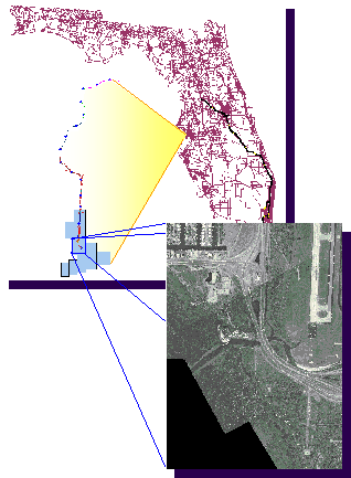
We evaluated several field collection systems for incorporation into the NPDES MS4 GIS system. Our evaluation research included the development of a bar code data collection method, data logger and pen-tablet. In addition, we field-tested several different manufactures of hardware and developed field data collection procedures. These tests were conducted at on the Veterans Expressway, near Tampa, Florida. This pilot site was selected because it has16 miles of self-contained roadway that travels through both urban and rural tracks. Additionally it is a new expressway with a complete set of updated construction plans. The Florida's Turnpike has available 1996 aerial photos of the Veterans Expressway, GIS-ready in 1-meter and 2/10-meter resolution. This site allowed us to test equipment and methodology under different roadway conditions ranging, from a four-lane highway to ten-lane with cloverleaf interchanges and fast moving city traffic. The documentation and aerial photos were used to check the soundness of the process and accuracy of the collected data.
Pre Field Collection Activities
As in any field project the more you anticipate challenges, research field conditions, and develop field event plans, the more efficient the team functions. Pre-planning included personnel training, site reconnaissances, site documentation, personnel interviews, mission planing, and communication setup. Each site has its own unique challenges or requirements to be considered. In our case the FDOT require the subcontractor to inform FDOT management of anticipated road work time frame, road crew dress code, and ensure all vehicles display flashing amber warning lights.
Personnel Training
The data collection personnel were certified Trimble GPS operators and went through 2 weeks of training, covering the NPDES MS4 data dictionary, NPDES MS4 structure identification, data collection field procedures, pen-tablet interface, and GPS review. It was important that every technician identified the structures the same way. One week was conducted in the field with close supervision to ensure data was being collected in the same manner by all. This is important for data editing and QA/QC procedure.
Site Reconnaissance
Before beginning data collection we conducted roadway reconnaissance through site visits and documentation review. We tried to determine any areas of concern such as heavy traffic patterns, dangerous intersections, or areas inaccessible because of waterways or swamps. Then a deployment plan was designed depending on the size of the team and the data collection method. We ran both 2 and 3 person teams. In rural areas with little traffic we used a leap frog method of collecting data, and in less accessible areas, due to traffic or barrier walls, we used the vehicle chauffeur method.
Site Documentation and Personnel Interviews
Next to field reconnaissance, site
documents and interviews of Turnpike field staff are the best methods of
gathering information on the roadways. The available construction plans
for the Turnpike roadways were often incomplete or plans were of an unknown
version, and as-builts were rarely created. The construction of the Turnpike
road system began in the 1960's and has been continuously added to or modified
over the years. This building process poses additional challenges to locating
accurate construction plans. Searching for and finding construction plans
are well worth the effort as they contain the locations of all the stormwater
structures, types, sizes, pipe sizes, materials, and other information.
Often interviews with senior FDOT field staff revealed a sequence of events that took place at a site. The roadway may have been built without the intersection having canals on each side. Later the canals were filled in or moved, or a new right-of-way was acquired, and sometime later an intersection was added. This information identifies three distinct time frames and three sets of plans that need to obtained and makes it obvious why the canals and right-of-ways do not line up on newer plans. Another source of information is permit documentation such as mitigation, water management, DEP, or drainage connection permits.
Mission Planning
Mission Planning allows you to increase the accuracy of the GPS positions you collect during time periods when satellite availability and geometry are optimal. Mission Planning programs charts the satellite availability and geometry over the collection location during the date and time of the collection event and assigns a numbers representing accuracy of satellite signal at chart intervals. This number is called PDOP (position dilution of precision) and it is the best overall indicator of constellation accuracy, although PDOP alone does not guarantee accurate positions. HDOP (horizontal dilution of precision) and VDOP (vertical dilution of precision) are components of PDOP, and are therefore always smaller than PDOP. Trimble's Pathfinder software has a component with which the user can create mission planning charts. The user must first load satellite data. Therefore, it is easier if you have access to the Internet to log onto a site, which has the satellite data and a Mission Planning program on line (Trimble's site is http://www.trimble.com/satview/).
Communication Setup
The field crews were located 150 to 300 miles from the office, therefore we needed to give the them several avenues of communication for data processing and trouble shooting, as well as for safety concerns. We explored several data transfer methods including; a 56 K modem, Ethernet card, disks, PCIMA hard drive, as well as 2-way radios and cellular phones. The team collected data with the Trimble GPS units and downloaded the day's data into a laptop, to view for discrepancies, and if necessary, scheduled a return trip the next day to recapture the data. This procedure worked well if the team maintained real-time signal during data collection, otherwise the data needed to be post processed. This process required base station data, this is also true during collection with the pen-tablet and the real-time signal was lost. GeoPlan/GeoFocus has this data available on their FTP site or other base station data could be retrieved from Internet sites with the use of a modem. This also gave the crew the ability to transfer data back to the office and e-mail messages. Each team member carried a 2-way radio, to keep in contact with other crewmembers.
Field Data Collection
We developed two methods for NPDES
MS4 baseline data collection. These methods both collect the same baseline
data needed for the 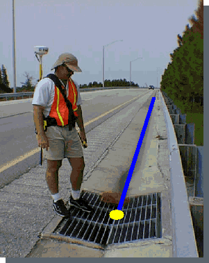 Turnpike
NPDES MS4 stormwater structure inventory. The field data collection process
is fairly straightforward.
Turnpike
NPDES MS4 stormwater structure inventory. The field data collection process
is fairly straightforward.
The field technician locates a stormwater structure, stands on it and collects a GPS location, then inputs the structure's attributes. The data logger has a menu style interface that the user can scroll through when collecting a features. Each structure falls in a feature category with associated attributes for the user to select. The pen-tablet application has graphical user interface (GUI) forms that allow the user to point and click through the forms. The pen-tablet gives the user more options to interact with the data. The data can be viewed immediately after collection, and additional themes can be viewed at the same time such as aerial photos, roadways, or canals. The data can be edited in the field. When using the pen-tablet method the user collects the GPS location and then populates GUI interface by selecting attributes, which maybe in on the these from presented in image, lists, Boolean, and entry fields.
The user then identifies the pipes that connect to the structure. The process of adding pipes is one of the major differences between using the data logger and the pen-tablet. When collecting with the data logger the user selects the pipe feature, takes one GPS point and must walk the pipe to the next structure. Or GPS point and walk on 20 feet and tag the pipe as a dangle to be connected in the office. The tagging method is useful for areas with high traffic flow to connecting structures on the opposite sides of the roadway. The pen-tablet application allows the user to see graphically where structures are located. So, if a pipe needs to be connected to a structure across a busy highway the user can select the structure on one side then the structure across the highway this action snaps a pipe between the structures. The description of each collection method interface will be expanded in a later section.
The next step is moving the crew up and down the road safely and efficiently. We use two methods the leapfrog and the vehicle chauffeur. The leapfrog method of data collection was most useful in open, low traffic areas with a two-person team or when using the Trimble data logger. This method allowed one person to start at a point as the other drives ahead a quarter of a mile and starts there. This method ensures that one data logger was used to collect data on both sides of the road, resulting in fewer pipe dangles and more accurate data. Each person has the opportunity to re-hydrate, and escape the sun (field workers in Florida are prone to heat exhaustion) than they drive the vehicle ahead of the other member a quarter of a mile and begin collecting.
The vehicle chauffeur, method involves one of the 2 or 3 team members driving other team members as close as possible to the structures to be collected or to drop a technician off on either side of the roadway and/or shuttling them to a new location as necessary. The three (3) member strategy permitted the third member to be available to immediately assist the technicians with off sets, transportation, or reviewing construction plans to better advise the technicians where to look for structures. The third member was in a position to enhance the safety of the team members. In addition, the driver was able to scout the area for potential danger and points of concern and relay the information to the technicians.
GPS Settings
Since Florida is surrounded by water, receiving the Coast Guard real-time beacon signal posed little problems, thus a GPS units collected in real-time mode. If the real time signal was lost for a prolonged period, the technician noted the time and date, and continued to collect without the real-time signal. To achieve structure location accuracy of 1 to 3 meters, 30 positions collected with a PDOP of less than 4, and 60 positions were collected when the PDOP was between 4 and 6. Unique structure ID numbers were generated using a concatenation of the Juliann date, time (to the second), and GPS unit number. This concatenation was performed when the data was passed through the "feature editor" in the case of data collected with the Trimble data logger. The pen-tablet application automatically assigned this unique ID number when a structure was collected. The user had the option to collect in English or Metric units, (this must be noted for the data logger method) when the data is updated through the "feature editor" the units are needed to enter the data correctly.
Trimble Pro XR Data Dictionary
The Trimble data dictionary has 2 hierarchy
levels (feature and attribute). The feature has attributes, and the attribute
can be entered through menu choices, or as a number with an assigned decimal
place, a string with assigned character length or as a Boolean responses.
When the data is exported through "Pathfinder Office" the user has several
formats from which to choice from. This process produces as many different
shapefiles as different features collected.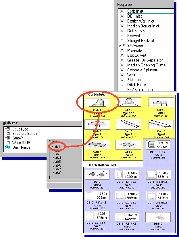
We defined 17 stormwater structure names (i.e. endwall, curb inlet, water treatment area, etc.) as features. Under these features was structure type, baffles, skimmers, grate, pipe size, and other specific attributes. The structure type attribute sometimes had as many as nine (9) different types (u-type endwall, winged endwall, mitered section endwall, etc.), which were put in a menu list for the user to chose from. Other attributes to be collected included; baffles, skimmer, grates, drains to the waters of the U.S. these attributes were assigned a Boolean response of yes or no. Some attributes such as pipe diameter or number-of-barrels were given a numeric format.
There are over 65 different structure types with non-distinctive names. For example, the differences between the ditch bottom inlet (DBI) 1 and DBI 2 is the size of the opening. So rather then having the technician memorizing 65 distinct structures, a display card with design images and description of each structure type, the data dictionary structure type identification names, and FDOT standard index number, were provided to each technician. For example, a DBI 2 and DBI 3 image look the same, the different in the structure type is the opening dimensions, so each DBI image is accompanied by it dimensions. A challenge with data collected by the data logger method is the pipes are not snapped to structure points.
This data was imported into the NPDES MS4 application database, which required the date to be reprocess into the applications database format. The application's database consisted of two shapefiles, one "point" shapefile containing the structure location and the other "line" shapefile containing the pipes location. Multiple relational databases are associated with each shapefile containing additional attributes and program activities. To enter data logger input into the NPDES MS4 application, GeoFocus, created a component called the "Feature Editor". This component was programmed in Avenue and loads the data from each of 17 shapefiles into either the structure point shapefile or the pipe "line" shapefile and its related databases. This component can also be used to edit the data.
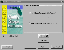
Feature Editor
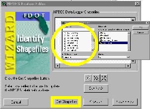
The "feature editor" will only import
data into the NPDES MS4 application properly, if the data was collected
using the data dictionary we designed. The feature editor has a series
of dialogs that step the user through the importing and data editing process.
The first dialog prompts the user to select the shapefiles to import and
the unit of measurement used to collect the data (i.e. feet, meter, etc.).
Then the user clicks the "update" button; and the program searches each
file for a predefined list of attributes and loads the information into
the application's database. The 17 separate shapefiles are reduced to two
shapefiles defined as structures, a point shapefile and as pipes, a line
shapefile. At this stage, however, the points and lines are not yet connected.
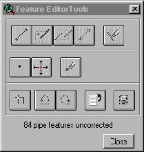
 The
next option is to "Edit Shape Features". One of two options are available
either 'batch process' or 'interactive process'. The 'batch process' automatically
compares point (structure) and line (pipe) location, a 10-meter radius
area-of-interest is created around each structure, if only one pipe intersected
this area and no other structure is within this area, one end of the pipe
is snapped to the structure. If more then one pipe or structure is found
in the area-of-interest, the process is repeated using is a 5-meter radius
area-of-interest. Once a pipe has been snapped to two structures it is
assigned a unique ID of the concatenation of the two structures unique
IDs. This process is successful on a high percentage of the structures
and pipes. The pipes without two IDs will have to be connected to a structure
by the user during the 'interactive process'.
The
next option is to "Edit Shape Features". One of two options are available
either 'batch process' or 'interactive process'. The 'batch process' automatically
compares point (structure) and line (pipe) location, a 10-meter radius
area-of-interest is created around each structure, if only one pipe intersected
this area and no other structure is within this area, one end of the pipe
is snapped to the structure. If more then one pipe or structure is found
in the area-of-interest, the process is repeated using is a 5-meter radius
area-of-interest. Once a pipe has been snapped to two structures it is
assigned a unique ID of the concatenation of the two structures unique
IDs. This process is successful on a high percentage of the structures
and pipes. The pipes without two IDs will have to be connected to a structure
by the user during the 'interactive process'.
The 'interactive process' steps through
the database looking for pipes without two structures IDs. Once a pipe
is identified, it is selected and bought into the viewer, if an aerial
photo of the area is loaded, it is added to the view, if the image is not
loaded the ID of the aerial image will be displayed so the user can add
appropriate images. The images and other themes such as roadways or canals,
along with hard copies of the construction plans assist the user in snapping
the pipes and structures together correctly. There is a custom palette
of called "Edit Tools", that assists the user in editing both the structures
and pipes. The tools include: adding, deleting, or moving points, adding
a line between two points (by snapping each end to a point), snapping a
line to a point, snapping two dangles together to make one line, adding
a line to a point by distance and azimuth, or delete a line. This palette
of tools can also be used to edit the data collect by the pen-tablet method,
if necessary.
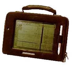
Trimble Pro XR and Pen-tablet NPDES MS4 Application
GeoFocus DANS product is a MapObjects-based field data collection tool designed for users of ArcView GIS and ArcInfo -- shapefiles, coverages, and verification with real-time GPS positioning and graphical displays position cursor and data collected. DANS includes the following:
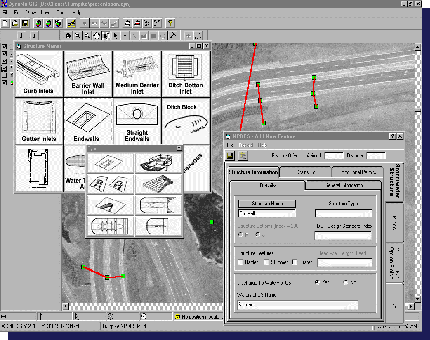 The
"Add Structure" interface has four (4) major tab forms, each tab may have
several subtabs. The first tab is the 'Stormwater Structure'. It contains
three (3) subtabs; Structure Information, Drains To, and Additional
Permits. The Structure Information tab is one of the most used
forms in the data collection process. On this tab is a button called "Structure
Name" (the same as in the Trimble Data Dictionary), that displays a palette
of 12 image buttons (images of stormwater structures). A miscellaneous
button contains the structures without types. This is why there are fewer
buttons, than the 17 features in the Data Dictionary. The user selects
the structure name by clicking a button. If the structure has types, a
palette of image buttons appears containing the structure's different types.
Once the user has made their final selection, the 'structure name', 'structure
type', and 'FDOT standard index number' fields are populated. Other attributes
have default values in accordance with the FDOT standards, and attributes
that do not apply to the structure are not available to select. The user
can change the attributes, if a visual inspection indicates the standard
does not apply to the structure being collected. For example, if the standard
for DBI indicates a grate, the application will check grate. Then, when
the structure is being collected and the grate is missing the user can
uncheck 'grate'. If the structure drains to the water of U.S. a string
field is made active to enter the name of the water body.
The
"Add Structure" interface has four (4) major tab forms, each tab may have
several subtabs. The first tab is the 'Stormwater Structure'. It contains
three (3) subtabs; Structure Information, Drains To, and Additional
Permits. The Structure Information tab is one of the most used
forms in the data collection process. On this tab is a button called "Structure
Name" (the same as in the Trimble Data Dictionary), that displays a palette
of 12 image buttons (images of stormwater structures). A miscellaneous
button contains the structures without types. This is why there are fewer
buttons, than the 17 features in the Data Dictionary. The user selects
the structure name by clicking a button. If the structure has types, a
palette of image buttons appears containing the structure's different types.
Once the user has made their final selection, the 'structure name', 'structure
type', and 'FDOT standard index number' fields are populated. Other attributes
have default values in accordance with the FDOT standards, and attributes
that do not apply to the structure are not available to select. The user
can change the attributes, if a visual inspection indicates the standard
does not apply to the structure being collected. For example, if the standard
for DBI indicates a grate, the application will check grate. Then, when
the structure is being collected and the grate is missing the user can
uncheck 'grate'. If the structure drains to the water of U.S. a string
field is made active to enter the name of the water body.
The "Drains To" tab is for structures that do not connect to another structure, but drain into lakes, canals, ditches, stormwater ponds or other facilities. Here the user can add additional information about the 'drain to' feature, this information is linked to the structure. In the case of a stormwater pond the additional information would be littoral zone information and an additional ID.
The "Additional Permits" tab allows the user to link the structure to additional permits. If both NPDES MS4 and mitigation permit cover a structure, the user could assign the mitigation permit ID to the structure. Typically this ID will be assigned in the office, through a spatial query of the mitigation permit area. If the structure had been previously collected the user can access the additional permit information through this tab.
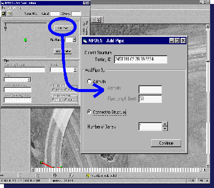 The
second major tab is "Pipes". The user will find a graphical representation
(a point and line(s)) of the selected structure and any pipes presently
snapped to the structure. This allows the user to know which pipes have
been collected. When adding a pipe the user can select a second structure
to snap the pipe between or create a pipe by distance and azimuth. The
pipe is added by snapping between the two structures, and is assigned an
ID, the concatenation of the two structures ID. The other method has only
one ID attached to the pipe making it a dangle-pipe. The user can enter
the pipe shape, diameter, and construction material by selecting the form's
attribute list or enter attributes manually. The tab also contains invert
fields, and flow direction fields, this information can be added in the
office.
The
second major tab is "Pipes". The user will find a graphical representation
(a point and line(s)) of the selected structure and any pipes presently
snapped to the structure. This allows the user to know which pipes have
been collected. When adding a pipe the user can select a second structure
to snap the pipe between or create a pipe by distance and azimuth. The
pipe is added by snapping between the two structures, and is assigned an
ID, the concatenation of the two structures ID. The other method has only
one ID attached to the pipe making it a dangle-pipe. The user can enter
the pipe shape, diameter, and construction material by selecting the form's
attribute list or enter attributes manually. The tab also contains invert
fields, and flow direction fields, this information can be added in the
office.
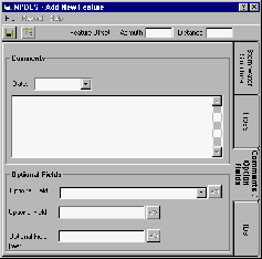
The third major tab is "Comments/Optional
Fields". The 'Comments' the user can attach a comment of up to 254 characters.
The "Optional Fields" were created to give the user greater flexibly. If
there is an additional attribute the user wants to collect, which we have
not anticipated elsewhere in the interface, the user has three optional
fields to enter the data, a string field of 254 characters, an integer
field, and a real number field. The user can change each field's caption.
The fields default captions are 'Optional Field', pushing the button at
the end of the field brings up a dialog where the user can enter a new
field caption, such as 'My ID'.
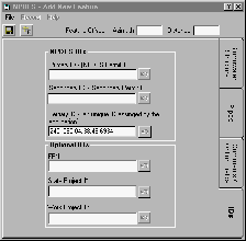 The
fourth major tab is "IDs". The FDOT has many ID's attached to sections
of roadways. The IDs in this tab are linked to the structure, and this
permits the user to query by any of these ID's. The default list of ID's
include:
The
fourth major tab is "IDs". The FDOT has many ID's attached to sections
of roadways. The IDs in this tab are linked to the structure, and this
permits the user to query by any of these ID's. The default list of ID's
include:
Projections
The Trimble Pro XR GPS unit captures location by X and Y coordinates. If the data logger is used to collect data, then Trimbles Pathfinder software has an assortment of export projections. If the pen-tablet is used to collect the data, then the DANS has a projector component, which projects the data being collected in several different projections, however, it can not re-project back ground themes, these must be loaded in the projection of choice.
Conclusion
We have developed two sound methods
for the collection of the Turnpike's NPDES MS4 stormwater structures GIS
inventory. These methods give the Turnpike the flexibility to use Trimble
GPS units presently in-house without purchase of new hardware or software
or they can purchase a pen-tablet with DANS software to run the graphically
visual collection method, which permits the user to manipulate the data
in the field. The pen-tablet will also be used with the inspections and
data manage components of the NPDES MS4 GIS application.